Transcription of 2ND GENERATION ELECTRIC ACTUATOR …
1 TheHighPerformanceCompanySERIES 702ND GENERATION ELECTRIC ACTUATOROPERATION AND maintenance MANUALBRAY Series 70 ELECTRIC ActuatorOperation and maintenance Manual1 Table Of COnTenTs: pageSafety in StructionS: definition of termS ..2 introduction ..3 principle of operation ..3 electrical operation ..3 mechanical operation ..3 manual override operation ..4 pre-in Stallation inStallation ..4 mounting to a valve ..4 field wiring ..4 multiple ACTUATOR wiring ..5 SerieS 70 on/off ACTUATOR with interpoSing relay board ..5 travel limit Switch and mechanical travel Stop adjuStment ..6 cloSe adjuStment ..6 open adjuStmentS ..7 baSic diSaSSembly and aSSembly inStructionS ..7 field or factory inStallable optionS torque SwitcheS operation ..8 heater ..9 Servo pro module ..9 external feedback potentiometer ..11 auxiliary SwitcheS ..11 auxiliary Switch configuration chart ..12 typical wiring diagramS form c (Spdt) SwitcheS on/off Service ..13 typical wiring diagramS modulating Service.
2 14 adjuStmentS, calibration & StatuS led of Servo pro ..15 quick connect receptacleS ..16 Spinner ..17 local control Station ..17 appendix a baSic toolS ..18 appendix b ACTUATOR troubleShooting chart ..19 Servo troubleShooting chart ..20 appendix c exploded view and partS li St of Size 003 and exploded view and partS li St of Size 008, 012 and 020 ..22 exploded view and partS li St of Size 030, 050 and 065 ..23 exploded view and partS li St of Size 130 and 180 ( ELECTRIC ) ..24 exploded view and partS li St of Size 130 and 180 (gear box) ..25for information on thiS product and other bray productS pleaSe viSit uS at our web page - Series 70 ELECTRIC ActuatorOperation and maintenance Hazard-free useThis device left the factory in proper condition to be safely installed and operated in a hazard-free manner. The notes and warnings in this document must be obeserved by the user if this safe condition is to be maintained and hazard-free operation of the device all necessary precautions to prevent damage to the ACTUATOR due to rough handling, impact, or improper storage.
3 Do not use abrasive compounds to clean the ACTUATOR , or scrape metal surfaces with any control systems in which the ACTUATOR is installed must have proper safeguards to prevent injury to personnel, or damage to equipment, should failure of system components Qualified PersOnnelA qualified person in terms of this document is one who is familiar with the installation, commissioning and operation of the device and who has appropriate qualifications, such as: Is trained in the operation and maintenance of ELECTRIC equipment and systems in accordance with established safety practices Is trained or authorized to energize, de-energize, ground, tag and lock electrical circuits and equipment in accordance with established safety practices Is trained in the proper use and care of personal protective equipment (PPE) in accordance with established safety practices Is trained in first aid In cases where the device is installed in a potentially explosive (hazardous)
4 Location is trained in the operation, commissioning, operation and maintenance of equipment in hazardous locationsWARNINGThe ACTUATOR must only be installed, commissioned, operated and repaired by qualified device generates large mechanical force during normal installation, commissioning, operation and maintenance must be performed under strict observation of all applicable codes, standards and safety is specifically made here to observe all applicable safety regualtions for actuators installed in potentially explosive (hazardous) insTruCTiOns - definiTiOn Of Termsread and fOllOW THese insTruCTiOnssaVe THese insTruCTiOnsWARNING indicates a potentially hazardous situation which, if not avoided, could result in death or serious a potentially hazardous situation which, if not avoided, may result in minor or moderate without the safety alert symbol indicates a potential situation which, if not avoided, may result in an undesirable result or state, including property damage.
5 !!!!BRAY Series 70 ELECTRIC ActuatorOperation and maintenance Manual3inTrOduCTiOnThe Bray Series 70 is a quarter turn ELECTRIC ACTUATOR with manual override for use on any quarter turn valve requiring up to 18000 of torque. Operating speeds vary between 6 to 90 seconds. PrinciPle Of OPeratiOnThe Series 70 ACTUATOR is basically divided into two internal sections; the power center below the switchplate, and the control center above the switchplate. Below the switchplate the capacitor and gearmotor with its spur geartrain drive a final non-backdriveable worm gear output. The override mechanism for manual operation is also housed here. Above the switch-plate is where user required, readily accessible components are placed. The camshaft assembly, limit switches, terminal strips, torque switches, heater, and servo are all placed here for easy access. External to the unit are found adjustable me-chanical travel stops, a large easy to read indicator, the unique manual override handwheel and dual conduit entry ports.
6 The external coating is a high quality polyester powder coat which has exceptional UV as well as chemical OPeratiOnThe motors used in the Bray Series 70 are either permanent induction split capacitor design (single phase AC power), SCI (Three Phase AC Power) or PM (DC Power). Travel limit switches are mechanical form (SPDT) with contacts rated at 10 amp ( PF), 1/2 HP 125/250 VAC. In cases where the torque capacity of the unit is exceeded to the point where the motor stalls and overheats, a thermal protector switch built into the motor windings will automatically disconnect the motor power. Once the motor cools sufficiently the thermal protector switch will reset. Optional torque switches are available in all units to prevent the possibility of stalling the motor, thus reduc-ing the necessity for an inoperable thermal cooldown period. Torque switches installed by Bray are factory adjusted to the output torque rating of the unit using electronic torque testing equipment.
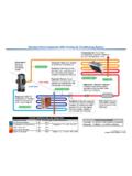
7 NOTICE Field adjustment of the torque switches is not Electrical SchematicNOTE: this is only a reference. For the actual wiring diagram refer to the diagram placed inside the ACTUATOR OPeratiOnMechanically, the ratio of the gearmotor determines the speed of the unit. The gearmotor utilizes high efficiency spur gears with various ratios for the different speeds. Initial gear reduction through the spur gears is then transferred to the worm shaft. The final gear reduction and output is through a non-backdriveable worm gear set. Positioning is determined by an indicator-cam shaft linked to the output shaft. In the declutchable condition the manual override drives the worm shaft when OVERRIDE SWITCHTRAVEL LIMIT SWITCHESCAPACITORMOTORTHERMAL PROTECTORTORQUE SWITCHESFIELDWIRING(OPTIONAL)Single phase power nuMbering SySteM reference chartSerieSSize cOdeSPeedPrOductStyleVOltagetriM70 AAAX113YZ536 Part nuMbertOrque( )SPeed, turn(Seconds)SuPPly(Z Voltage)70-003X-113yz-53630030/150/1/2/3 /470-005X-113yz-53650030/150/1/2/3/470-0 08X-113yz-53680030/15/60/1/2/3/4/5/6/7/8 70-012X-113yz-536120030/15/60/1/2/3/4/5/ 6/7/870-020X-113yz-536200030/15 0/1/2/3/4/5/6/7/870-030X-113yz-536300030 /18 0/2/3/4/5/6/7/870-050X-113yz-536500030/1 8 0/2/3/4/5/6/7/870-065X-113yz-536650030 0/2/4/5/6/7/870-1306-113yz-536130001200/ 2/4/5/6/7/870-1806-113yz-536180001200/2/ 4/5/6/7/8 Use this chart as a guide to interpret the S70 ELECTRIC ACTUATOR part - DESIGNATES THE SPEEDX:12245 Sec.
8 30181568Y - DESIGNATES STYLEAB asic Unit - DeclutchableDWith Interposing Relay Board**Only available for 24 VAC, 120 VAC, or 220 VAC unitsZ - DESIGNATES THE VOLTAGEZ:012345678 Voltage:120 VAC12 VDC24 VDC24 VAC220 VAC380V3-PH400V3-PH440V3-PH480V3-PHBRAY Series 70 ELECTRIC ActuatorOperation and maintenance Manual4 manual OVerride OPeratiOn (declutchable)The manual override operates similar to a watch adjusting knob. To engage the manual override, simply pull the hand-wheel to its outermost position. A yellow stripe is revealed for visual indication that the unit cannot run electrically. The two handwheel positions, engaged and disengaged, are held in place with the use of spring plungers. The handwheel remains in position until physically moved. Rotating the handwheel in the clockwise direction will rotate the output shaft in the same clockwise (closed) direction and vice-versa. CAUTIONA label on the handwheel hub warns users not to exceed a specific rim pull force, for each size of ACTUATOR .
9 If the rim pull force is exceeded, the roll pin securing the handwheel onto the manual override shaft is designed to shear, thus preventing more serious internal gearing StOrageUnits are shipped with two metal screw-in plugs in order to prevent foreign matter from entering the unit. NOTICETo prevent condensation from forming inside these units, maintain a near constant external temperature and supply power to the optional heater internal to the tO a ValVeAll Bray Series 70 ELECTRIC actuators are suitable for direct mounting on Bray butterfly valves. With proper mounting hardware, the S70 ACTUATOR can be installed onto other quarter-turn valves or standard mounting position for the ACTUATOR is to orient the unit with its handwheel in a vertical plane and parallel to the pipeline. If the ACTUATOR is to be mounted on a vertical pipe, it is recommended that the unit be po-sitioned with the conduit entries on the bottom to prevent condensation from entering the ACTUATOR by way of the conduit.
10 In all cases, the conduit should be positioned to prevent drainage into the ACTUATOR should be mounted to the valve as follows:1. Manually operate the ACTUATOR until the output shaft of the ACTUATOR is in line with the valve stem. If possible, select an intermediate position ( valve disc/stem and ACTUATOR both half open).2. Place the proper adapter, if required, onto the valve stem. It is recommended that a small amount of grease be applied to the adapter to ease Mount the ACTUATOR onto the valve stem. It may be necessary to swing or manually override the ACTUATOR to align the bolt Install the furnished mounting studs by threading them all the way into the ACTUATOR Fasten in place with the furnished hex nuts and lock WiringWARNINGTurn off all power and lock out service panel before installing or modifying any electrical ACTUATOR is provided with two (2) conduit entries (one for power and one for control).