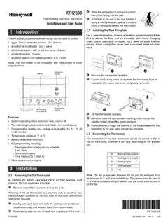
Transcription of Series with RedLINK Installation Guide
1 VisionPRO Series with RedLINK Installation GuideTMTMORORW ired Directly to Equipment2 Wires for power orBattery Only (no wires)2 Wires for power orBattery Only (no wires)Dual Powered - C Wire or Battery(C wire or Wire Saver required to use RedLINK accessories) RedLINK to Equipment Interface ModuleRedLINK to TrueZONE Wireless AdapterTM 2 Current display. Underlined label signifies the current control buttons. Use to change settings for Fan or System Select options to: set schedules, view equipment status, change IAQ settings, access installer options*, status. Shows system mode (heat/cool), outdoor temperature and humidity (with optional outdoor sensor).Current schedule. Shows desired temperature and schedule conditions. Shows indoor temperature and Light. On when alert message is active or system is set to Em Heat.
2 Flashes for battery-only power ; on continuous for 24 Card Port. Use card to load settings and dealer to key features* Password is the date startedFollow these basic steps to install this thermostat, link it with the wireless accessories, and set installer Installing the thermostat2 Powering optional RedLINK accessories3 Performing initial setup4 Finding your password (Date Code) To add or remove RedLINK accessories To make changes to Installer Setup To perform an Installer TestResidential/R sidentiel1-800-468-1502 , Golden Valley, MN 55422 RoHs CompliantConformit RoHsAssembled in MexicoAssembl au MexiqueTH8321R1001 11324 Residential/R sidentiel1-800-468-1502 , Golden Valley, MN 55422 RoHs CompliantConformit RoHsAssembled in MexicoAssembl au MexiqueTH8321R1001 11324 Thermostat (back view)Password (Date Code) 3 NOTE.
3 For best RedLINK performance, mount thermostats at least 2 feet Separate wallplate from thermostat. Press button on top and pull to remove the Connect Insert supplied AA alkaline batteries for primary or backup : When the thermostat is NOT used with the Equipment Interface Module or the TrueZONE Wireless Adapter, a C wire is required for For 24 VAC primary power , connect common side of transformer to C Mount wallplate as shown. Mount new wallplate using screws and anchors included with the thermostat. Drill 3/16-in holes for drywall. Drill 7/32-in holes for (back view)Wallplate (back view)WallplateS1S1 WYGW2Y2 ACKRCRU1U1U2U2S1S1O/BYGAUX-EY2L/AThermos tatButton1 Installing the thermostat Wire the thermostat. Is the thermostat wired directly to the equipment? If the thermostat is wired directly to the equipment:a Refer to the table and wiring diagrams on the next Turn on 24 VAC NOW.
4 24 VAC (C wire) is required to connect RedLINK accessories. If the thermostat is used with an Equipment Interface Module or TrueZONE Wireless Adapter, power the thermostat using Rc and C terminals or with : The relay outputs and inputs on the thermostat do not function when used with an Equipment Interface Module or TrueZONE Wireless PUMPS1S1 WYGW2Y2AS1S1O/BYGAUX-EY2L/AKRCRU1U1U2U2 CCONVENTIONALHEAT Remove coin cell battery Remove tab to activate coin cell battery. NOTE: Coin cell battery saves time and date during a power Mount thermostat on wallplate. Align thermostat at bottom and snap into place as DURINGINSTALLATIONREMOVE DURINGINSTALLATIONT hermostatCoin cell battery tabWallplate 5 Terminal DesignationsConventional SystemHeat PumpTerminalDescriptionTerminalDescripti onCCommon wire from secondary side of cooling transformer (if 2 transformers).
5 CCommon wire from secondary side of cooling *Cooling power . RcCooling power . R*Heating power . RHeating power . WHeat Stage 1O/BChangeover valve for heat Stage 2 AUX-EBackup Heat/Emergency HeatYCompressor Stage 1 YCompressor Stage 1Y2 Compressor Stage 2Y2 Compressor Stage 2 GFan RelayGFan RelayAConnect to Economizer Module or Lighting Panel (TOD).L/AConnect to Compressor Monitor, Zone Panel, Economizer Module or Lighting Panel (TOD).U1 / U1 Universal relay for humidification, dehumidification, ventilation, or a stage of / U1 Universal relay for humidification, dehumidification, ventilation, or a stage of / S1 Universal input for a wired indoor, outdoor or discharge / S1 Universal input for a wired indoor, outdoor or discharge **Connect to K on Wire Saver module. K**Connect to K on Wire Saver module.
6 * Remove factory installed jumper for two transformer systems.** The THP9045A1023 Wire Saver module is used on heat/cool systems when you only have four wires at the thermostat and you would like the thermostat to be powered with a common wire. Use the K terminal in place of the Y and G terminals on conventional or heat pump systems to provide control of the fan and the compressor through a single wire the unused wire then becomes your common wire. See THP9045 instructions for more , DEHUM OR VENT TRANSFORM-ERTHERMOSTATPOWERED HUMIDIFIER, DEHUMIDIFIER OR VENTILATORCKRCRU1U1120 VAC24 VACCRSYSTEMTRANSFORMERTHERMOSTATNON-POWE RED HUMIDIFIER, DEHUMIDIFIER OR VENTILATORFIELD INSTALL JUMPER BETWEEN R AND U1 CONNECTING A HEAT OR COOL STAGE TO U1 DEHUMIDIFICATION WITH LOW SPEED FANNON-POWERED HUMIDIFIER, DEHUMIDIFIER OR VENTILATORPOWERED HUMIDIFIER, DEHUMIDIFIER OR VENTILA-TORWire the thermostat universal relay to the low speed fan for dehumidification control at the equipment.
7 The thermostat relay can be set to normally open or normally closed in the thermostat installer terminals are normally open dry contacts when set up for a stage of heating or must install a field jumper if the stage of heat-ing or cooling is powered by system transformer. Do NOT install a field jumper if the stage of heating has its own open, dry contactsNormally closed, dry contacts1 CKRCRU1U1120 VAC24 VACCRSYSTEMTRANSFORMERTHERMOSTATDEHUMIDI FICATION WITH LOW SPEED FANFIELD INSTALL JUMPER BETWEEN R AND U1OR2 CKRCRU1U1120 VAC24 VACCRTRANSFORMERTHERMOSTATHEAT STAGE 3, COOL STAGE 3, BACKUP HEAT STAGE 2 FOR HEAT PUMPS, OR GEOTHERMAL RADIANT HEAT1 Install batteries in RedLINK accessories. Portable Comfort Control Wireless Outdoor Sensor* Wireless Indoor Sensor* Wireless Entry/Exit Remote* Wireless Vent and Filter Boost Remote** Requires setup.
8 See Installer Setup options in Step Connect gateway to internet and connect to Connect RedLINK Internet Gateway to router or modem with Ethernet cable (RJ45). Connect gateway s power cord to an electrical outlet that is not controlled by a wall : If the thermostat is wired directly to the equipment, 24 VAC (C wire) is required to connect RedLINK accessories. Turn on 24 VAC before performing initial setup in Step 3. M36568 INTERNETPOWERREDLIN KInitial setup options define the type of system you are installing: Residential or commercial Non-zoned or zoned Used with or without an Equipment Interface Module (THM5421) Used with or without the TrueZONE Wireless Adapter (THM4000) Follow prompts on the screen to select the appropriate : If you are connecting the thermostat to the TrueZONE Wireless Adapter (THM4000), refer to the TrueZONE instructions to link the thermostat and RedLINK accessories.
9 Then go to Step When you see the prompt Connect RedLINK Accessories? Touch No or Ye s. If you select No, continue to Step If you select Ye s, you will be prompted to Press Connect on New Accessories. Continue to Step RedLINK Accessories?APPLICATION residential2 Powering optional RedLINK accessories3 Performing initial setup 7 Connect each RedLINK : Accessories must be at least 2 feet away from the thermostat during the linking While the Press Connect message is displayed (listening mode), press and quickly release the CONNECT button on each new RedLINK After a short delay (up to 15 seconds), check thermostat to confirm the connection of each RedLINK accessory. Touch s or t to review the Touch Done at the thermostat after all new RedLINK accessories are : Thermostat displays a countdown timer while in the listening mode.
10 If it detects no activity for 15 minutes, it exits listening Finish the initial the setup by selecting the desired options. Touch Done after you select the last option you want to thermostat now displays its Home screen and the thermostat setup is TYPE programmableM33985 MCR33972 Outdoor Sensorhas been addedMCR34058 Press Connect onNew mode 8 To add or remove RedLINK accessories To make changes to Installer Setup To perform an Installer TestFinding your passwordYou can find the date code on the back of the thermostat, or1 Touch Select Dealer Scroll down to see the Date RedLINK accessories to the thermostat1 Touch Select Installer Enter password (date code) and touch Select Wireless ManagerReset To DefaultsMCR33977 Enter password0 0 0 0 MCR33976 Installer OptionsMCR33975TH8321R1001 Date Code.