Transcription of SERVICE PARTS 1200 Series Air Dryers INSTRUCTIONS For …
1 TP-92116 Revised 8-98 TP-9211616579/MeritorRevised 8-98 Printed in the USA Copyright Meritor WABCO , 1998 Page 1 SERVICE PARTSINSTRUCTIONS Installing the Meritor WABCO System Saver 1000 and 1200 Series Air Dryers For Use on Tractors, Trucks and Buses with Air BrakesInstallation Requirements12345 or 24-Volt Air Dryer23 Capscrew (1/2"-13 UNC 2A x )33 Lock Washer (1/8" thick)41 Heater Power Harness51 Pressure-Controlled Check Valve TP-92116 Revised 8-9816579/Meritor Page 2 Copyright Meritor WABCO , 1998 Printed in the USA SERVICE Notes You must follow your company safety procedures when you install the System Saver 1000 and 1200 Series air Dryers . Meritor WABCO uses the following types of notes to give warning of possible safety problems and to give information that will prevent damage to the air A warning indicates procedures that must be followed exactly.
2 Serious personal injury can occur if the procedure is not A caution indicates procedures that must be followed exactly. If the procedure is not followed, damage to equipment or components can occur. Serious personal injury can also occur in addition to damaged or malfunctioning equipment or symbol is used to indicate fasteners that must be tightened to a specific torque value. NOTE A note indicates an operation, procedure or instruction that is important for correct installation. A note can also give information that will make installation quicker and easier. Meritor WABCO System Saver Single Cartridge Air Dryer Publications MM34 Maintenance ManualPB-96134 PARTS BookTP-9672 Air Dryer Application GuidelinesTP-977226 x 40 Troubleshooting Guide Wall ChartTP-97101 Troubleshooting Guide (laminated card)T-97105V Troubleshooting and Repair Video (30 min.)
3 To order literature contact the Meritor Customer Support Center at 800-535-5560. part Number Selection Guide (See page 3 for application information)SeriesVoltage (100 Watts)Replacement KitID Tag Number 1200 Standard Application12 voltsR955205432 413 001 01200 Standard Application24 voltsR955206432 413 002 01200E Use with Holset E Compressor12 voltsR955207432 413 006 01200E Use with Holset E Compressor24 voltsR955208432 413 009 01200U Discharge Line (Continuous Flow) Installation12 voltsR955210432 413 007 01200U Discharge Line (Continuous Flow) Unloader Installation24 voltsR955211432 413 021 0 TP-9211616579/MeritorRevised 8-98 Printed in the USA Copyright Meritor WABCO , 1998 Page 3 Introduction This installation manual contains basic installation INSTRUCTIONS for standard air systems and includes special INSTRUCTIONS for installing the Pressure-Controlled Check Valve (PCCV).
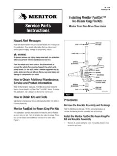
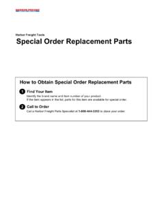
4 It also includes System Saver 1000 and 1200 air dryer diagnostics. Read all INSTRUCTIONS before proceeding with your installation. Application Information: Cubic Feet per Minute (CFM)Less than 25 CFMN ormal Duty CycleLess than 30%Typical Compressor 2 Minutes or LessLoaded Time WARNINGS To prevent serious eye injury, always wear safe eye protection when you perform vehicle maintenance or SERVICE . Do not work around or under the vehicle unless it is parked on a level surface. Use blocks to keep the vehicle from moving. A moving vehicle can cause serious personal injury and damage. Remove all air from the air system before servicing any component in the air system. Pressurized air can cause serious personal injury. Basic Installation INSTRUCTIONS TYPICAL INSTALLATION FOR SYSTEM SAVER 1000 AND 1200 Series AIR DRYERGOVERNORCOMPRESSORINTAKE LINEUNLOADERPORTGOVERNORPORTCOMPRESSORDR YER INLETCOMPRESSORDISCHARGELINEPURGE VALVEDRYER OUTLETCHECKVALVESYSTEMRESERVOIRSYSTEMRES ERVOIRSYSTEMRESERVOIRSYSTEMRESERVOIRSUPP LY(WET) TANKPRESSURE-CONTROLLEDCHECK VALVETO BRAKE SYSTEM TP-92116 Revised 8-9816579/Meritor Page 4 Copyright Meritor WABCO , 1998 Printed in the USA Mounting the Air Dryer 1.
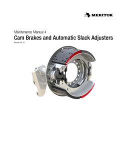
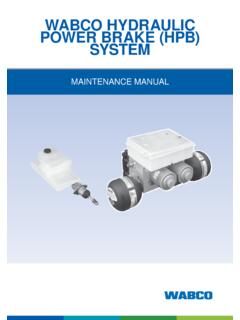
5 Park the vehicle on a level surface, stop the engine, set the parking brake and block the Drain pressurized air from all reservoirs to 0 psi (0 bar). Open all draincocks to expel collected Inspect the vehicle for a suitable mounting location that meets the following criteria. The air dryer will operate most efficiently when you follow these Mount the air dryer where cool air can flow around it .. but not directly in the vehicle wind stream .. and at least 12 inches away from any heat Mount the air dryer LOWER than the compressor so that water in the delivery line flows into the air dryer. There should be no water traps (low points) in the line before or after the air Mount the air dryer in a vertical position or within 30 of vertical, with the desiccant cartridge at the Allow at least two inches (51 mm) of clearance above the top of the air dryer for servicing the desiccant Mount the air dryer in a location where it is not subject to direct splash or spray from a Apply the adhesive-backed template to the selected location.
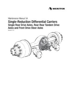
6 Figure 1 . Figure " / 73 " / 52 " / 105 mmAir Dryer Installation Template TP-9211616579/MeritorRevised 8-98 Printed in the USA Copyright Meritor WABCO , 1998 Page 5 NOTE Check the vehicle manufacturer s specifications before drilling into the frame member. 5. Drill 9/16-inch holes at each cross mark. Use a mounting bracket, if necessary. Figure 2 or 3 .6. Mount the air dryer using the capscrews and lock washers Tighten each capscrew to 22-30 lb-ft (30-40 N O m). Connecting the Air Lines NOTE Use pipe sealant or teflon tape on all air fittings. NOTE The reference to nylon tubing throughout this manual refers to SAE J844 air brake nylon tubing. 1. Connect the delivery line from the compressor to the air dryer inlet port (1/2" NPTF, marked 1 ) with 1/2-inch-ID minimum stainless-steel braided teflon hose. The air dryer will operate most efficiently when the following guidelines are The delivery line should follow a DOWNHILL route to the inlet port (Figure 4), free of kinks and sags, which cause water Air temperature entering the dryer should be less than 175 F ( C).
7 The delivery line must be at least feet ( m), but most vehicles require a greater length to achieve this The delivery line should not exceed 20 feet ( m), or moisture within the line can freeze, blocking air Insulate a delivery line with a length of over 10 feet ( m). Figure 2 Figure 3 Figure 4 TP-92116 Revised 8-9816579/Meritor Page 6 Copyright Meritor WABCO , 1998 Printed in the USA 2. Connect the air dryer outlet port (1/2-inch NPTF, marked 21 ) to the inlet of the supply (wet) tank with 1/2-inch or 5/8-inch nylon tubing. Figure 5 . 3. Connect the air governor unloader port to the air dryer control port (1/4-inch NPTF, marked 4 ) with 1/4-inch or 3/8-inch nylon tubing. Figure 6 .4. Check all fittings for leaks before proceeding. Connecting the Heater The System Saver 1000 and 1200 Series air Dryers are available in 12- or 24-volt models; each has a 100-watt heater.
8 Each kit contains a two-wire harness which supplies power to the unit. Be sure to select the correct power source for the air dryer model. Using the wrong voltage can cause malfunction and even damage the unit. Check vehicle manufacturer specifications for exact wiring Connect one of the leads to a good vehicle ground. Attach the other lead to a line that is powered with the ignition in the run position, and not powered with the ignition off. A 15-amp fuse is recommended for this line for 12 volts and amps for 24 Press the male plug on the end of the power cable into the receptacle on the side of the dryer. Plug must be inserted until the latch snaps over the tab on the mating connector. Figure 7 .3. Insulate and seal all electrical splices and properly secure the harness. Figure 5 Figure 6 Figure 7 TP-9211616579/MeritorRevised 8-98 Printed in the USA Copyright Meritor WABCO , 1998 Page 7 Determine the Correct Pressure-Controlled Check Valve (PCCV) Placement for the System Saver 1000 and 1200 Series Air Dryer The regeneration volume is determined by how much compressed air is pumped through the air dryer during each compressor cycle.
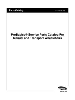
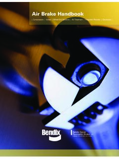
9 The following chart shows the proper sizing of the system and the volume of the reservoirs contributing to the regeneration volume required for a given installation. The reservoirs contributing to regeneration will determine the placement of the PCCV in the system. Since the air dryer will take approximately 10 psi from the contributing reservoirs, the volume for regeneration will be a function of the reservoir Total System Size is the sum of all the air tanks to be filled on all vehicles that the compressor will be filling. For instance, if the tractor has a total air system of 6000 in 3 (supply 900 in 3 , primary 3200 in 3 , secondary 1900 in 3 ) and it pulls a lead single trailer with 1400 in 3 , a single axle dolly with 1400 in 3 , and a second single axle trailer with 1400 in 3 , the total system size is 10,200 in 3 . Looking at the chart and finding 10,200 in 3 at the bottom, reading up and over shows the system needs 2856 in 3 of reservoir volume contributing to regeneration.
10 From this volume, 10 psi would be taken for regeneration. In this case, installing the PCCV on the primary tank gives adequate regeneration volume (supply 900 in 3 + primary 3200 in 3 = 4100 in 3 ). Figure 8 . Formula for Total System Size Use the formula below to compute total system size. r Total System Size = Sum of all reservoir tanks an air compressor must SERVICE in the vehicle s air system . Example: (IN 3 ) r Supply (Wet) Tank900 Primary Reservoir Tank3200 Secondary Reservoir Tank1900 Tractor s Total Air System6000(IN 3 ) r Lead Single Axle Trailer1400 Single Axle Dolly1400 Second Single Axle Trailer1400 Total Load Pulled:4200 r Total Combination Vehicle System Size (IN 3 )The Air CompressorMust SERVICE 6000 + 4200 =10,200 Figure 8500040003000200010000 Total reservoir volume in30500010,000 Volume of reservoirs contributingto regeneration in3 TP-92116 Revised 8-9816579/Meritor Page 8 Copyright Meritor WABCO , 1998 Printed in the USA Installing the Pressure-Controlled Check Valve (PCCV) NOTE The pressure-controlled check valve replaces the one-way check valve on either the secondary or primary SERVICE reservoir.