Transcription of Sheet Resistance Mapping for GaN-Based Light …
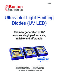
1 1 Sheet Resistance Mapping for GaN-Based Light - emitting Diodes using lehighton Electronics LEI-1510 Instrument Thomas Gessmann and E. Fred Schubert The Future Chips Constellation Department of Electrical, Computer, and Systems Engineering Department of Physics, Applied Physics, and Astronomy Rensselaer Polytechnic Institute Troy NY 12180 Light - emitting diodes (LEDs) based on GaN, GaInN, and AlGaN semiconductors are capable of emitting in the UV, violet, blue, cyan, and green spectral range. III-V nitride LEDs are epitaxially grown on substrates, most commonly on sapphire, but also on Si, SiC, AlN, GaAs. The Light - emitting active region, where charge carriers recombine, is typically comprised of a periodical stack of quantum wells separated by barriers as shown in Fig. 1. Electrons and holes injected into the multi-quantum well (MQW) region are confined inside the wells. Due to the high carrier concentration inside the wells, the radiative recombination rate is strongly increased compared with a bulk active region.
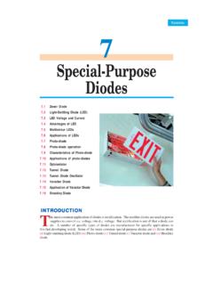
2 The active region is embedded between the n-type and p-type confinement (or cladding) regions of larger-bandgap material which is essentially transparent for Light emitted by the active region. Figure 1: Schematic representation of an undoped multiple-quantum well (MQW) bandstructure. An electron blocking layer is employed to avoid electron leakage out of the MQW region. The inset shows the shift of electron and hole ground-state energies due to quantum confinement. The electrical properties of LEDs depend strongly on the conductivity of the p-type and n-type layers. In GaN at room temperature, typical electron mobilities n are about a factor of 50 larger than hole mobilities p at a given dopant concentration. Therefore, the resistivity of n-type GaN material is usually much lower than the resistivity of p-type GaN. Fig. 2 shows a GaN-Based LED structure grown on an insulating substrate with an active p-n junction region embedded between p-type and n-type cladding layers.
3 Because the structure is grown on an insulating substrate, mesa-etching and a side-by-side contact configuration are employed. The electrical conductivities of the cladding layers impact the current transport in a p-side up mesa-structured LED in two ways: First, the upper p-type does not spread the current very well in lateral direction due to the low conductivity of p-type GaN. To alleviate this problem, semitransparent metal contacts may be deposited to cover the entire p-type top surface area. Second, the current tends to crowd in regions close to the edge of the mesa mountain as shown in Fig. 2. This results in non-uniform Light emission. A high intensity is emitted at the edge of the mesa and the intensity decreases with increasing distance from the mesa edge. 2It has been shown that the current density decreases exponentially with increasing distance x from the mesa edge [1].
4 The characteristic current spreading length Ls over which the current density drops to 1/e of its initial value depends on the thickness tn and the resistivity n of the n-type layer according to nnppc/)( + =ttLs (1) where c and p denote the specific contact Resistance of the p-type metal contact and the resistivity of the p-type layer, respectively. In Eq. (1), tp corresponds to the thickness of the p-type layer. The current crowding effect leads to non-uniform Light emission and undesired device heating, resulting in shortened device lifetimes. The n-type layer is of crucial importance for the avoidance of current crowding. Specifically, the n-type Sheet Resistance needs to be sufficiently low so that the junction current is uniform. It is therefore desirable to determine the Sheet Resistance of the n-type layer.
5 Typical values for good device performance are an n-type layer thickness of 2 m and a Sheet Resistance < 50 Ohm per square ( / ). Figure 2: Schematic structure of a GaN-Based LED epitaxially grown on an insulating substrate. Depending on the conductivities and thicknesses of the p- and n-type layers the current crowds around the mesa edge. Non-destructive Sheet Resistance measurements are based on the absorption of RF-power by the generation of eddy currents in a thin semiconductor or metal layer. For that purpose the sample is placed between two RF coils, of which one acts as RF emitter and the other one as RF receiver. The method has been pioneered by Miller et al. [2]. Sheet Resistance instruments are commercially available from lehighton Electronics, Inc. < >. This note reports contactless Sheet Resistance measurements that have been performed on a GaInN/GaN blue LED wafer using a lehighton Sheet Resistance mapper LEI-1510.
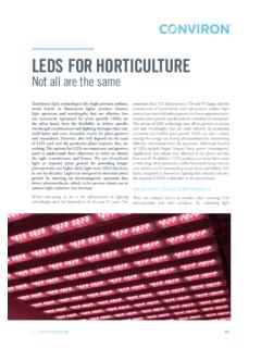
6 The LED structure was grown by metal-organic vapor phase epitaxy in an Aixtron RF-200/4RF-S reactor at Rensselaer Polytechnic Institute using H2 and N2 carrier gases and the precursors TMGa, TEGa, TMIn, Cp2Mg, NH3 and SiH4. The substrate was a 2 sapphire wafer oriented in the [001] direction. From in-situ optical reflectometry during growth, the thickness of the n-type cladding layer was determined to be about 3 m. In the Sheet Resistance measurement, eddy currents are generated almost exclusively in the n-type layer due to its much higher conductivity than the p-type top cladding layer. The Sheet Resistance values shown in Fig. 3 can therefore be fully attributed to the Sheet Resistance of the n-type layer. The map consists of 28 measurements taken at different positions of the wafer surface using an edge exclusion of mm. From the measured data points an average Sheet Resistance Ravg = / with a standard deviation Rs = / was obtained.
7 The results correspond to a low intra-wafer Sheet Resistance uniformity Rs/Ravg = % which is an excellent value. Visual inspection of the wafer showed no interference fringes except within a distance of about 4 mm of the wafer edges indicating excellent thickness uniformity. The value of the thickness uniformity was determined to be % using white- Light interferometry. Thus the Sheet Resistance map reflects the n-type 3Si doping concentration uniformity across the wafer. The excellent thickness and doping uniformities are due to a very uniform temperature distribution across the wafer during epitaxial growth and due to wafer rotation. This rotation accounts for the approximately circular shape of the contour lines in Fig. 3. Figure 3: Sheet Resistance map of the n-type cladding layer in a GaN-Based LED structure. The map consists of 28 contactless Sheet Resistance measurements performed by a LEI 1510 unit.
8 The thickness of the buried n-type layer is about 3 m. In conclusion, Sheet Resistance measurements using lehighton Electronics LEI-1510 instrument have proven to be very useful to evaluate the doping uniformity and conductivity of the n-type cladding layer in GaN-Based LEDs. The contactless nature of the measurement allows non-destructive access to the buried n-type layer of an LED structure. Optimization of the n-type conductivity is important to avoid high device Resistance and current crowding, and obtain low forward voltage, device heating, and junction temperature. References [1] Guo X. and Schubert E. F. Current crowding and optical saturation effects in GaInN/GaN Light - emitting diodes grown on insulating substrates Appl. Phys. Lett. 78 (2001) 3337; see also: Schubert E. F. Light emitting Diodes (Cambridge University Press, Cambridge UK, 2003) [2] Miller G. L., Robinson D.
9 A. H., and Wiley J. D., Contactless measurement of semiconductor conductivity by radio-frequency-free-carrier power absorption Rev. Sci. Instrum. 47, No. 7, (1976) 799