Transcription of Special-Purpose Diodes - Talking Electronics
1 INTRINTRINTRINTRINTRODUCTIONODUCTIONODUC TIONODUCTIONODUCTIONThe most common application of Diodes is rectification. The rectifier Diodes are used in powersupplies to convert voltage into voltage. But rectification is not all that a diode cando. A number of specific types of Diodes are manufactured for specific applications inthis fast developing world. Some of the more common Special-Purpose Diodes are (i) Zener diode (ii) light -emitting diode (LED) (iii) Photo- diode (iv) Tunnel diode (v) Varactor diode and (vi) Shockleydiode. diode diode (LED) Voltage and Current of LED LEDs of LEDs operation of of diode of Varactor DiodeSpecial-PurposeDiodes7126 Principles of Zener DiodeA zener diode is a special type of diodethat is designed to operate in the reversebreakdown region.
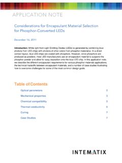
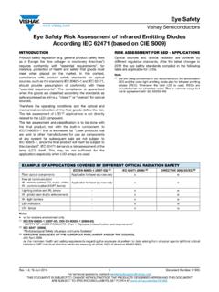
2 An ordinary diodeoperated in this region will usually bedestroyed due to excessive is not the case for the zener zener diode is heavily doped toreduce the reverse breakdown causes a very thin depletion a result, a zener diode has a sharpreverse breakdown voltage VZ. This isclear from the reverse characteristic ofzener diode shown in Fig. Notethat the reverse characteristic drops inan almost vertical manner at reversevoltage VZ. As the curve reveals, twothings happen when VZ is reached :(i)The diode current increases rapidly.(ii)The reverse voltage VZ across the diode remains almost other words, the zener diode operated in this region will have a relatively constant voltageacross it, regardless of the value of current through the device. This permits the zener diode to beused as a voltage regulator. For detailed discussion on zener diode , the reader may refer to chapter 6of this light -Emitting diode (LED)A light -emitting diode (LED) is a diode that gives off visible light when forward Diodes are not made from siliconor germanium but are made by using elements likegallium, phosphorus and arsenic.
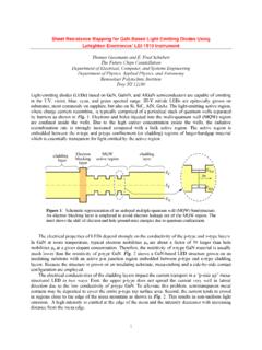
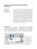
3 By varying thequantities of these elements, it is possible to producelight of different wavelengths with colours that in-clude red, green, yellow and blue. For example, whena LED is manufactured using gallium arsenide, it willproduce a red light . If the LED is made with galliumphosphide, it will produce a green When light -emitting diode (LED) is for-ward biased as shown in Fig. (i), the electronsfrom the n-type material cross the pn junction andrecombine with holes in the p-type material. Recallthat these free electrons are in the conduction bandand at a higher energy level than the holes in the va-lence band. When recombination takes place, the re-combining electrons release energy in the form of heat and light . In germanium and silicon Diodes , light -emitting diodeFig. Diodes 127almost the entire energy is given up in the form of heat and emitted light is insignificant.
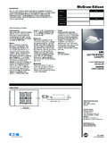
4 However, inmaterials like gallium arsenide, the number of photons of light energy is sufficient to produce quiteintense visible light .(i)(ii)Fig. (ii) shows the schematic symbol for a LED. The arrows are shown as pointing awayfrom the diode , indicating that light is beingemitted by the device when forward biased. Al-though LEDs are available in several colours(red, green, yellow and orange are the most com-mon), the schematic symbol is the same for allLEDs. There is nothing in the symbol to indi-cate the colour of a particular LED. Fig. the graph between radiated light and theforward current of the LED. It is clear from thegraph that the intensity of radiated light is di-rectly proportional to the forward current of LED Voltage and CurrentThe forward voltage ratings of most LEDs is from 1V to 3V and for-ward current ratings range from 20 mA to 100 mA.
5 In order that currentthrough the LED does not exceed the safe value, a resistor RS is con-nected in series with it as shown in Fig. The input voltage is VS andthe voltage across LED is VD. Voltage acrossRS=VS VD Circuit current,IF=SDSVVR Example What value of series resistor is required to limit the current through a LED to20 mA with a forward voltage drop of V when connected to a 10V supply ?Solution. Series resistor,RS=SDFVVI HereVS= 10 V;VD = V;IF = 20 mA = 20 10 3 AFig. Principles of Electronics RS=310 10 = 420 Note that resistor RS is also called current-limiting What is current through the LED in the circuitshown in Fig. ? Assume that voltage drop across the LED is 2 Current through LED,IF=SDSVVR Here VS = 15 V;VD = 2 V;RS = k = 103 IF= 10 = 10 3 A = Advantages of LEDThe light -emitting diode (LED) is a solid-state light source.
6 LEDs have replaced incandescent lampsin many applications because they have the following advantages :(i)Low voltage(ii)Longer life (more than 20 years)(iii)Fast on-off switchingProtecting LED against reverse bias. The LEDs have low reverse volt-age ratings. For example, a typical LED may have a maximum reverse voltagerating of 3V. This means that if a reverse voltage greater than 3 V is applied tothe LED, the LED may be destroyed. Therefore, one must be careful not to useLEDs with a high level of reverse bias. One way to protect a LED is to connecta rectifier diode in parallel with LED as shown in Fig. If reverse voltagegreater than the reverse voltage rating of LED is accidentally applied, the rec-tifier diode will be turned on. This protects the LED from Multicolour LEDsA LED that emits one colour when forward biased and another colour when reverse biased is calleda multicolour commonly used schematic symbol for these LEDs is shown in Fig.
7 Multicolour LEDs(i)(ii)Fig. Diodes 129actually contain two pn junctions that are connected in reverse-parallel they are in parallel withanode of one being connected to the cathode of the other. If positive potential is applied to the topterminal as shown in Fig. (i), the pn junction on the left will light . Note that the device currentpasses through the left pn junction. If the polarity of the voltage source is reversed as shown inFig. (ii), the pn junction on the right will light . Note that the direction of device current hasreversed and is now passing through the right pn LEDs are typically red when biased in one direction and green when biased in theother. If a multicolour LED is switched fast enough between two polarities, the LED will produce athird colour. A red/green LED will produce a yellow light when rapidly switched back and forthbetween biasing Applications of LEDsThe LED is a low-power device.
8 The power rating of a LED is of the order of milliwatts. This meansthat it is useful as an indicator but not good for illumination. Probably the two most common appli-cations for visible LEDs are (i) as a power indicator (ii) seven-segment display.(i) As a power indicator. A LED can beused to indicate whether the power is on or shows the simple use of the LED as a powerindicator. When the switch S is closed, power isapplied to the load. At the same time current alsoflows through the LED which lights, indicatingpower is on. The resistor RS in series with the LEDensures that current rating of the LED is not ex-ceeded.(ii) Seven-segment display. LEDs are often grouped to form seven-segment (i) shows the front of a seven segment display. It contains seven LEDs (A, B, C, D, E, F andG) shaped in a figure of *8. Each LED is called a **segment.
9 If a particular LED is forward biased,that LED or segment will light and produces a bar of light . By forward biasing various combinationsof seven LEDs, it is possible to display any number from 0 to 9. For example, if LEDs A, B, C, D and Gare lit (by forward biasing them), the display will show the number 3. Similarly, if LEDs C, D, E, F, Aand G are lit, the display will show the number 6. To get the number 0, all segments except G are lit.(i)(ii)Fig. (ii) shows the schematic diagram of seven-segment display. External series resistors areincluded to limit currents to safe levels. Note that the anodes of all seven LEDs are connected to a*Note that LEDs A, B, C, D, E and F are arranged clockwise from the top with LED G in the middle.**Each LED is called a segment because it forms part of the character being 130 Principles of Electronicscommon positive voltage source of +5 V.
10 This arrangement is known as *common-anode type. Inorder to light a particular LED, say A, we ground the point A in Fig. (ii). It forward biases the LEDA which will be Photo-diodeA photo- diode is a reverse-biased silicon or germanium pn junction in which reverse current in-creases when the junction is exposed to reverse current in a photo- diode is directly proportional to the intensity of light falling on itspn junction. This means that greater the intensity of light falling on the pn junction of photo- diode ,the greater will be the reverse When a rectifier diode is reverse biased, it has a very small reverse leakage same is true for a photo- diode . The reverse current is produced by thermally generated electron-hole pairs which are swept across the junction by the electric field created by the reverse voltage. Ina rectifier diode , the reverse current increases with temperature due to an increase in the number ofelectron-hole pairs.