Transcription of Silicon PIN Photodiode - Vishay
1 Semiconductors Rev. , 23-Aug-111 Document Number: 81643 For technical questions, contact: DOCUMENT IS SUBJECT TO CHANGE WITHOUT NOTICE. THE PRODUCTS DESCRIBED HEREIN AND THIS DOCUMENTARE SUBJECT TO SPECIFIC DISCLAIMERS, SET FORTH AT PIN PhotodiodeDESCRIPTIONTEMD5080X01 is a PIN Photodiode with enhanced bluesensitivity. The miniature surface mount package (SMD)include a chip with mm2 sensitive area, covered by Package type: surface mount Package form: top view Dimensions (L x W x H in mm): 5 x x Radiant sensitive area (in mm2): AEC-Q101 qualified Enhanced blue photo sensitivity: S (400 nm)rel > 30 % Peak sensitivity at 940 nm Suitable for visible and near infrared radiation Low junction capacitance Fast response times Angle of half sensitivity: = 65 Floor life: 72 h, MSL 4, acc.
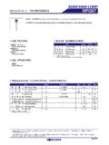
2 J-STD-020 Lead (Pb)-free reflow soldering Compliant to RoHS Directive 2002/95/EC and inaccordance to WEEE 2002/96/ECNote**Please see document Vishay Material Category Policy High speed photo detectorNote Test conditions see table Basic Characteristics Note MOQ: minimum order quantity20535 PRODUCT SUMMARYCOMPONENTIra ( A) (deg) (nm)TEMD5080X0160 65350 to 1100 ORDERING INFORMATIONORDERING CODEPACKAGINGREMARKSPACKAGE FORMTEMD5080X01 Tape and reelMOQ: 1500 pcs, 1500 pcs/reelTop viewABSOLUTE MAXIMUM RATINGS (Tamb = 25 C, unless otherwise specified)PARAMETERTEST CONDITIONSYMBOLVALUEUNITR everse voltageVR25 VPower dissipationTamb 25 CPV215mWJunction temperatureTj100 COperating temperature rangeTamb- 40 to + 100 CStorage temperature rangeTstg- 40 to + 110 CSoldering temperatureAcc.
3 Reflow solder profile fig. 8 Tsd260 CThermal resistance junction/ambientRthJA350K/W Semiconductors Rev. , 23-Aug-112 Document Number: 81643 For technical questions, contact: DOCUMENT IS SUBJECT TO CHANGE WITHOUT NOTICE. THE PRODUCTS DESCRIBED HEREIN AND THIS DOCUMENTARE SUBJECT TO SPECIFIC DISCLAIMERS, SET FORTH AT CHARACTERISTICS (Tamb = 25 C, unless otherwise specified) Fig. 1 - Reverse Dark Current vs. Ambient Temperature Fig. 2 - Relative Reverse Light Current vs. Ambient TemperatureBASIC CHARACTERISTICS (Tamb = 25 C, unless otherwise specified)PARAMETERTEST voltageIF = 50 voltageIR = 100 A, E = 0V(BR)25 VReverse dark currentVR = 10 V, E = 0 Iro210nADiode capacitanceVR = 0 V, f = 1 MHz, E = 0CD90pFVR = 3 V, f = 1 MHz, E = 0CD3040pFOpen circuit voltageEe = 1 mW/cm2, = 950 nmVo350mVTemperature coefficient of VoEe = 1 mW/cm2, = 950 nmTKVo- circuit currentEe = 1 mW/cm2, = 950 nmIk50 ATemperature coefficient of IkEe = 1 mW/cm2, = 950 light currentEe = 1 mW/cm2, = 400 nm,VR = 5 VIra18 A EV = 100 lx, CIE illuminant A, VR = 5 AEe = 1 mW/cm2, = 950 nm.
4 VR = 5 VIra60 ATemperature coefficient of IraCIE illuminant A TKIra = 950 nmTKIra of half sensitivity 65degWavelength of peak sensitivity p940nmRange of spectral bandwidth to 1100nmNoise equivalent powerVR = 10 V, = 400 x 10-13W/ HzRise timeVR = 5 V, RL = 50 , = 850 nmtr40nsFall timeVR = 5 V, RL = 50 , = 850 nmtf40ns20406080110100100010094 8403VR = 10 VTamb - Ambient Temperature ( C)Iro - Reverse Dark Current (nA) 8409VR=5V = 950 nm100806040200I - Relative Reverse Light CurrentT - Ambient Temperature ( C)ambra rel Semiconductors Rev. , 23-Aug-113 Document Number: 81643 For technical questions, contact: DOCUMENT IS SUBJECT TO CHANGE WITHOUT NOTICE.
5 THE PRODUCTS DESCRIBED HEREIN AND THIS DOCUMENTARE SUBJECT TO SPECIFIC DISCLAIMERS, SET FORTH AT Fig. 3 - Reverse Light Current vs. Irradiance Fig. 4 - Diode Capacitance vs. Reverse Voltage Fig. 5 - Relative Spectral Sensitivity vs. Wavelength Fig. 6 - Relative Radiant Sensitivity vs. Angular - Photo Current ( A)raEv- Illuminance (lx)100020538VR = 5 VCIE illuminant A02040608020539CD - Diode Capacitance (pF)VR - Reverse Voltage (V) = 0f = 1 - Wavelength (nm)S ( )rel - Relative Spectral - Relative Radiant Sensitivity94 30 10 20 40 50 60 70 80 - Angular Displacement Semiconductors Rev. , 23-Aug-114 Document Number: 81643 For technical questions, contact: DOCUMENT IS SUBJECT TO CHANGE WITHOUT NOTICE.
6 THE PRODUCTS DESCRIBED HEREIN AND THIS DOCUMENTARE SUBJECT TO SPECIFIC DISCLAIMERS, SET FORTH AT DIMENSIONS in millimetersDrawing-No.: : 3; indicated tolerances Semiconductors Rev. , 23-Aug-115 Document Number: 81643 For technical questions, contact: DOCUMENT IS SUBJECT TO CHANGE WITHOUT NOTICE. THE PRODUCTS DESCRIBED HEREIN AND THIS DOCUMENTARE SUBJECT TO SPECIFIC DISCLAIMERS, SET FORTH AT DIMENSIONS in millimetersREEL DIMENSIONS in millimeters2053720874 Semiconductors Rev. , 23-Aug-116 Document Number: 81643 For technical questions, contact: DOCUMENT IS SUBJECT TO CHANGE WITHOUT NOTICE. THE PRODUCTS DESCRIBED HEREIN AND THIS DOCUMENTARE SUBJECT TO SPECIFIC DISCLAIMERS, SET FORTH AT PROFILE Fig.
7 7 - Lead (Pb)-free Reflow Solder Profileacc. J-STD-020 DDRYPACKD evices are packed in moisture barrier bags (MBB) toprevent the products from moisture absorption duringtransportation and storage. Each bag contains a LIFETime between soldering and removing from MBB must notexceed the time indicated in J-STD-020:Moisture sensitivity: level 4 Floor life: 72 hConditions: Tamb < 30 C, RH < 60 %DRYINGIn case of moisture absorption devices should be bakedbefore soldering. Conditions see J-STD-020 orrecommended conditions:192 h at 40 C (+ 5 C), RH < 5 %or96 h at 60 C (+ 5 C), RH < 5 %.050100150200250300050100150200250300 Time (s)Temperature ( C)240 C245 Cmax.
8 260 Cmax. 120 smax. 100 s217 Cmax. 30 smax. ramp up 3 C/smax. ramp down 6 C/s19841255 CLegal Disclaimer Revision: 08-Feb-171 Document Number: 91000 Disclaimer ALL PRODUCT, PRODUCT SPECIFICATIONS AND DATA ARE SUBJECT TO CHANGE WITHOUT NOTICE TO IMPROVE RELIABILITY, FUNCTION OR DESIGN OR OTHERWISE. Vishay Intertechnology, Inc., its affiliates, agents, and employees, and all persons acting on its or their behalf (collectively, Vishay ), disclaim any and all liability for any errors, inaccuracies or incompleteness contained in any datasheet or in any other disclosure relating to any makes no warranty, representation or guarantee regarding the suitability of the products for any particular purpose or the continuing production of any product.
9 To the maximum extent permitted by applicable law, Vishay disclaims (i) any and all liability arising out of the application or use of any product, (ii) any and all liability, including without limitation special, consequential or incidental damages, and (iii) any and all implied warranties, including warranties of fitness for particular purpose, non-infringement and merchantability. Statements regarding the suitability of products for certain types of applications are based on Vishay s knowledge of typical requirements that are often placed on Vishay products in generic applications. Such statements are not binding statements about the suitability of products for a particular application.
10 It is the customer s responsibility to validate that a particular product with the properties described in the product specification is suitable for use in a particular application. Parameters provided in datasheets and / or specifications may vary in different applications and performance may vary over time. All operating parameters, including typical parameters, must be validated for each customer application by the customer s technical experts. Product specifications do not expand or otherwise modify Vishay s terms and conditions of purchase, including but not limited to the warranty expressed as expressly indicated in writing, Vishay products are not designed for use in medical, life-saving, or life-sustaining applications or for any other application in which the failure of the Vishay product could result in personal injury or death.