Transcription of Simulation and comparison of SPWM and SVPWM control …
1 VOL. 5, NO. 7, JULY 2010 ISSN 1819-6608. ARPN Journal of Engineering and Applied Sciences 2006-2010 Asian Research Publishing Network (ARPN). All rights reserved. Simulation AND comparison OF SPWM AND SVPWM control . FOR THREE PHASE INVERTER. K. Vinoth Kumar, Prawin Angel Michael, Joseph P. John and Dr. S. Suresh Kumar School of Electrical Sciences, Karunya University, Coimbatore, Tamilnadu, India E-Mail: ABSTRACT. A voltage source inverter is commonly used to supply a three-phase induction motor with variable frequency and variable voltage for variable speed applications. A suitable pulse width modulation (PWM) technique is employed to obtain the required output voltage in the line side of the inverter. The different methods for PWM generation can be broadly classified into Triangle comparison based PWM (TCPWM) and Space Vector based PWM ( SVPWM ). In TCPWM methods such as sine-triangle PWM, three phase reference modulating signals are compared against a common triangular carrier to generate the PWM signals for the three phases.
2 In SVPWM methods, a revolving reference voltage vector is provided as voltage reference instead of three phase modulating waves. The magnitude and frequency of the fundamental component in the line side are controlled by the magnitude and frequency, respectively, of the reference vector. The highest possible peak phase fundamental is very less in sine triangle PWM when compared with space vector PWM. Space Vector Modulation (SVM) Technique has become the important PWM technique for three phase Voltage Source Inverters for the control of AC Induction, Brushless DC, Switched Reluctance and Permanent Magnet Synchronous Motors. The study of space vector modulation technique reveals that space vector modulation technique utilizes DC bus voltage more efficiently and generates less harmonic distortion when compared with Sinusoidal PWM (SPWM) technique. In this paper first a model for Space vector PWM is made and simulated using MATLAB/SIMULINK software and its performance is compared with Sinusoidal PWM.
3 The Simulation study reveals that Space vector PWM utilizes dc bus voltage more effectively and generates less THD when compared with sine PWM. Keywords: PWM, SVPWM , three phase inverter, total harmonic distortion. INTRODUCTION against a common triangular carrier to generate PWM. AC drives are more predominant than dc drives. pulses for the three phases. The frequency of the carrier Ac drives requires high power variable voltage variable signal is very high compared to the modulating signal. The frequency supply. The research in Pulse width modulation magnitude and frequencies of the fundamental component schemes has been intensive in the last couple of decades. in the line side are controlled by changing the magnitude PWM techniques have been used to achieve variable and frequency of the modulating signal. It is simple and voltage and variable frequency in ac-dc and dc-ac linear between 0% and of six step voltage values, converters. PWM techniques are widely used in different which results in poor voltage utilization.
4 Voltage range has applications such as variable speed drives (VSD), static to be extended and harmonics has to be reduced. frequency changers (SFC), un-interruptible power supplies In SVPWM methods, the voltage reference is (UPS) etc. The main problems faced by the power provided using a revolving reference vector. In this case electronic design engineers are about the reduction of magnitude and frequency of the fundamental component harmonic content in inverter circuits. The classical square in the line side are controlled by the magnitude and wave inverter used in low or medium power applications frequency, respectively, of the reference voltage vector. suffers from a serious disadvantage such as lower order Space vector modulation utilizes dc bus voltage more harmonics in the output voltage. One of the solutions to efficiently and generates less harmonic distortion in a enhance the harmonic free environment in high power three phase voltage source inverter.
5 Converters is to use PWM control techniques. The objective of PWM techniques was to fabricate a sinusoidal SPACE VECTOR PULSE WIDTH MODULATION. AC output whose magnitude and frequency could both be Space Vector Modulation (SVM) was originally restricted. developed as vector approach to Pulse Width Modulation PWM switching strategies not only addresses the (PWM) for three phase inverters. It is a more sophisticated primary issues viz, less THD, effective dc bus utilization technique for generating sine wave that provides a higher etc but also take care of secondary issues like EMI voltage to the motor with lower total harmonic distortion. reduction , switching loss, better spreading of Harmonics The main aim of any modulation technique is to obtain over the spectrum. Real-time method of PWM generation variable output having a maximum fundamental can be broadly classified into Triangle comparison based component with minimum harmonics. Space Vector PWM. PWM (TCPWM) and Space Vector based PWM ( SVPWM ) method is an advanced; computation intensive ( SVPWM ).
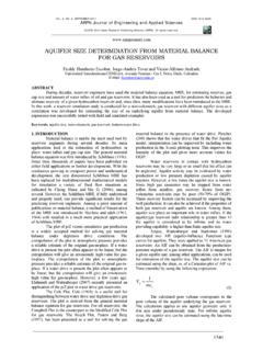
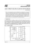
6 PWM method and possibly the best techniques for In TCPWM methods such as sine-triangle PWM, variable frequency drive application. three phase reference modulating signals are compared 61. VOL. 5, NO. 7, JULY 2010 ISSN 1819-6608. ARPN Journal of Engineering and Applied Sciences 2006-2010 Asian Research Publishing Network (ARPN). All rights reserved. A space vector PWM based on space vector representation of the voltages in the The circuit model of a typical three-phase - plane. The - components are found by Clark's voltage source PWM inverter is shown in Figure-1. S 1 transformation. Space Vector PWM ( SVPWM ) refers to to S 6 are the six power switches that shape the output, a special switching sequence of the upper three power which are controlled by the switching variables a, a', b, transistors of a three-phase power inverter. It has been b', c and c'. When an upper switch is switched on, , shown to generate less harmonic distortion in the output when a, b or c is 1, the corresponding lower transistor voltages and/or currents applied to the phases of an AC.
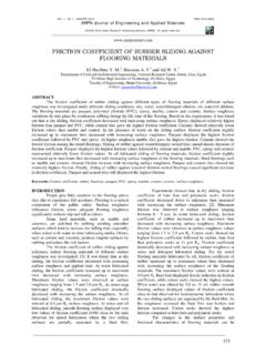
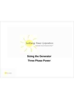
7 Is switched off, , the corresponding a', b' or c' is 0. motor and to provide more efficient use of dc input Therefore, the on and off states of the upper switch S1, S3 voltage. Because of its superior performance and S5 can be used to determine the output voltage. characteristics, it has been finding widespread application SVPWM is a different approach from PWM modulation, in recent years.. Figure-1. Three phase voltage source inverter. SPACE VECTOR CONCEPT the stationary dq reference frame that consists of the The space vector concept, which is derived from horizontal (d) and vertical (q) axes as depicted in Figure-2. the rotating field of induction motor, is used for From Figure-2, the relation between these two reference modulating the inverter output voltage. In this modulation frames is below technique the three phase quantities can be transformed to their equivalent two-phase quantity either in f dq0 = K s f abc (4). synchronously rotating frame (or) stationary frame.
8 From these two-phase components, the reference vector magnitude can be found and used for modulating the inverter output. The process of obtaining the rotating space vector is explained in the following section, considering the stationary reference frame. Considering the stationary reference frame let the three-phase sinusoidal voltage component be, Va = VmSin t (1). Vb = VmSin( t-2 /3) (2). Vc = VmSin( t-4 /3) (3). When this three-phase voltage is applied to the AC. machine it produces a rotating flux in the air gap of the AC. machine. This rotating resultant flux can be represented as single rotating voltage vector. The magnitude and angle of the Figure-2. The relationship of abc reference frame rotating vector can be found by means of Clark's and stationary dq reference frame. Transformation as explained below in the stationary reference frame. To implement the space vector PWM, the voltage equations in the abc reference frame can be transformed into 62.
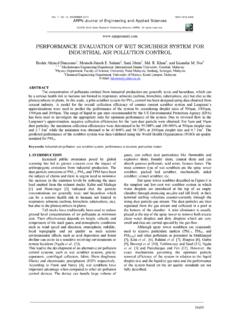
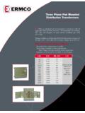
9 VOL. 5, NO. 7, JULY 2010 ISSN 1819-6608. ARPN Journal of Engineering and Applied Sciences 2006-2010 Asian Research Publishing Network (ARPN). All rights reserved. 1 -1 -1 eight switching patterns. One simple method of 2 2 approximation is to generate the average output of the 2 T. 3 3 , f = f f f , f abc = [ f a fb f c ] , T. K s = 0 - - inverter in a small period T to be the same as that of 3 2 2 dq0 d q 0 . 1 1 1 Vref in the same period 2 2 2 .. and f denotes either a voltage or a current variable. As described in Figure-2. This transformation is equivalent to an orthogonal projection of [a b c] t onto the two-dimensional perpendicular to the vector [1 1 1] t (the equivalent d-q plane) in a three-dimensional coordinate system. As a result, six non-zero vectors and two zero vectors are possible. Six non-zero vectors (V1-V6) shape the axes of a hexagonal as depicted in Figure-3, and supplies power to the load. The angle between any adjacent two non-zero vectors is 60 degrees.
10 Meanwhile, two zero vectors (V0 and V7) and are at the origin and apply zero voltage to the load. The eight vectors are called the basic space vectors and are denoted by (V0, V1, V2, V3, V4, V5, V6, V7). The same transformation can be applied to the desired output voltage to get the desired reference voltage vector,Vref in Figure-3. Basic switching, vectors and sectors. the d-q plane. The objective of SVPWM technique is to approximate the reference voltage vector Vref using the SWITCHING STATES. Table-1. Switching patterns and output vectors. Switching Line to neutral Line to line voltage Voltage vectors voltage vectors Van Vbn Vcn Vab Vbc V0. A B C. V0 0 0 0 0 0 0 0 0 0. V1 1 0 0 2/3 -1/3 -1/3 1 0 -1. V2 1 1 0 1/3 1/3 -2/3 0 1 -1. V3 0 1 0 -1/3 2/3 -1/3 -1 1 0. V4 0 1 1 -2/3 1/3 1/3 -1 0 1. V5 0 0 1 -1/3 1/3 2/3 0 -1 1. V6 1 0 1 1/3 -2/3 1/3 1 -1 0. V7 1 1 1 0 0 0 0 0 0. For 180 mode of operation, there exist six "0" denote the switch in OFF. Table-1 gives the details of switching states and additionally two more states, which different phase and line voltages for the eight states.