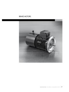
Transcription of ThREE-PhaSE MOTORS - AsEG Antriebstechnik
1 33tHree-PHaSe MOTORS - TEChNiCal CaTalOguE 1039/12 ThREE-PhaSE MOTORS34tHree-PHaSe MOTORS - TEChNiCal CaTalOguE 1039/12 Direction of cable entriesterminal BoxThe location of the terminal box in standard design is on top; on the right or on the left are possible. MOTORS 71-160 frame size have removable feet for easy change of terminal box positionFor MOTORS with mountings IM B6, IM B7, IM B8, IM V5, IM V6 the location of the terminal box is related to an IM B3 position of the entry openings can be adjusted to suit the existing connection facilities by turning through 90.
2 Should special accessories be used (temperature detectors, anti-condensation heating, etc.) please MOTORS in standard design, the cable gland does not belong to our scope of delivery. For plastic terminal boxes, only plastic glands may be used (shock protection).When using screened leads, a metal terminal box is DESigN frame size Degree of Max. cable terminal Max. external protection thread for cable entry section thread cable diam. Metric 1) Pg 2) mm 2 mm 56 - 71 IP 55 1 x M16/1 x M20 1 x Pg 11/1 x Pg M4 12 80 IP 55 1 x M25/1 x M20 1 x Pg x Pg 16 M4 16 90 - 112 IP 55 1 x M25/1 x M20 1 x Pg x Pg 16 4 M5 16 132 IP 55 2 x M32 2 x Pg 21 4 M5 20 160 IP 55 2 x M40 2 x Pg 29 16 M6 28 180 IP 55 2 x M40/1 x M20 35 M8 28 200 IP 55 2 x M40/1 x M25 35 M8 34 225 IP 55 2 x M50/1 x M25 50 M10 34 250 - 280 IP 55 2 x M50/1 x M25 50 M10 40 315 IP 55 2 x M63/1 x M25 3) 185 M12 481) Pitch )
3 Pg thread to DIN 40 430 (on request)3) Terminal box with unscrewable cable entry plate35tHree-PHaSe MOTORS - TEChNiCal CaTalOguE 1039/12 frame g4 A B Material size h 56 98 91 93 Plastic UL 94 V0 63 103 91 93 Plastic UL 94 V0 71 112 91 93 Plastic UL 94 V0 80 129 111 116 Plastic UL 94 V0 90 138 111 116 Plastic UL 94 V0 100 145 111 116 Plastic UL 94 V0 112 161 111 116 Plastic UL 94 V0 132 198 133 133 Aluminium 160 238 150 150 Aluminium 180 268 187 162 Cast Iron 200 300 233 186 Cast Iron 225 335 233 186 Cast Iron 250 366 260 218 Cast Iron 280 408 260 218 Cast Iron 315
4 530 320 280 Cast IronStandard deSiGn1) On frame size 56-63 the terminal box is supplied displaced towards the non-drive end frame g4 A B Material size h 56 100 94 94 Aluminium 63 105 94 94 Aluminium 71 114 94 94 Aluminium 80 139 110 110 Aluminium 90 148 110 110 Aluminium 100 155 110 110 Aluminium 112 171 110 110 Aluminium 180 285 209 220 Cast Iron 200 310 241 246 Cast Iron 225 334 272 254 Cast Iron 250 375 272 254 Cast Iron 280 409 272 254 Cast IronSPecial deSiGnTerminal box on topBAg4hTerminal box at the sideABg4hrightABg4hleft 1)
5 BAg4hMEChaNiCal DESigN36tHree-PHaSe MOTORS - TEChNiCal CaTalOguE 1039/12 StAR-DEltA StARtIngStar-delta starting allows a peak current reduction. It can be used only when the reduced starting torque obtained is higher than the resistant torque. Actually, it should be noted that the torque of an induction squirrel-cage motor is directly proportional to the square of the voltage. MOTORS whose rated voltage with delta connection corresponds to the mains voltage, can be started with the star-delta MOTORS can be supplied with windings designed for star-delta starting (for example: 400 V / 690 V Y).
6 V1W1U1L2L3L1U2V1W2U1V2W1 Star connectionV2U2L3W1V1L1W2U1L2V1U1W1 Delta connectionconnection diaGramSWindings of standard ThREE-PhaSE single speed MOTORS can be connected either in star or delta COnnECtIOnA star connection is obtained by connecting W2, U2, V2 terminals to eachother and the U1, V1, W1 terminals to the mains. The phase current and voltage are:Iph = In ; Uph = Un / 3where In is the line current and Un the line voltage referred to the star COnnECtIOnA delta connection is obtained by connecting the end of a phase to the beginning of the next phase current Iph and the phase voltage Uph are:Iph = In / 3 ; Uph = Unwhere In and Un are referred to the delta DESigN37tHree-PHaSe MOTORS - TEChNiCal CaTalOguE 1039/12 Pole-cHanGinG motorSStandard pole-changing MOTORS are designed for single voltage and direct-on-line starting.
7 When the ratio between the two speeds is from 1 to 2, the standard MOTORS have one single winding (Dahlander connection). For the other speeds, the MOTORS have two separate - two separate windings2W1W2V1VL32U1UL1 Low speedL2L32W1WL2L12V1V2U1 UHigh speedAM - Dahlander connection /yyLow speedHigh speedL3L1L22W1W2V1V2U1U2W2VL31W1VL12U1UL 22U2V2W2U2W2V1U1V1W1V1U1 WAMv - Dahlander connection y/yyHigh speed2W2V1W1U1V2U2U2V2 WLow speed1W2W1V2VL3L11U2UL22W2VL31W1VL12U1UL 21V1U1 WElECTRiCal DESigN38tHree-PHaSe MOTORS - TEChNiCal CaTalOguE 1039/12 MOTORS frame sizes 90 upwards in standard design are suitable for operation on static frequency converters.
8 Taking into account the following remarks: Maximum converter output voltage 500V at peak voltages 1460V and du/dt 13 kV/us. For higher converter output voltages or stresses, a special insulation is required. With square characteristic of the load torque, MOTORS can be driven with their rated torque. For constant torque, the rated torque of MOTORS with internal cooling must be reduced due to reduced cooling air inlet. Depending on the control range, the use of an external fan would be advisable. The MOTORS frame sizes 90 112 are suitable for a maximum output frequency of the converter of 60 Hz ( applications with square torque, control range 1:10, such as pumps and fans).
9 For higher frequencies, a special range with type designation AMI is available on request. From frame size 132 upwards, MOTORS designed /Y 230/400 V, 50 Hz can be operated in delta with a maximum frequency of 87 Hz (observe mechanical limit speed).The MOTORS frame size 56 80 can be operated on single-phase converters up to maximum 60 Hz. (Special range with type designation AMI for operation on ThREE-PhaSE converters with output voltage 400 V and output frequency > 60 Hz).The electrical values and dimensions of the range AMI in frame size 56 to 112 are identical to AM MOTORS (see data tables pages 49-51).
10 Note: 75 kW, 2 poles and up - insulated bearing are recomended when inverter cooling12321 Internal cooling MOTORS 2p = 2 Internal cooling MOTORS 2p = 4-8no field weakeningwith field weakeningf [Hz]MU/MNTorque caracteristics of ThREE-PhaSE MOTORS driven by frequency MOTORS DRiVEN BY FREQuENCY CONVERTERSnOISED epending on the operating point and converter type, converter-fed MOTORS produce between approx. 4 - 10 dB(A) higher noise values than when supplied from the mains. For MOTORS driven with a frequency over 50 Hz, more fan noise is produced.