Transcription of L6235 three phase brushless DC motor driver - st.com
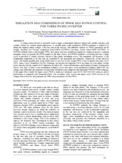
1 1/39AN1625 APPLICATION NOTEO ctober 20031 INTRODUCTIONFor small- motor applications many appliance designers favor modern three phase brushless DC motors be-cause of the high efficiency (as great as 95%) and small size for a given delivered power. Designers have tohandle control logic, torque and speed control, power-delivery issues and ensure safe operation in every loadcondition. The L6235 is a highly integrated, mixed-signal power IC that allows to easily design a complete motorcontrol system for BLDC motor . Figure 1 shows the L6235 block diagram. The IC integrates six Power DMOS,a centralized logic circuit to decode hall effect sensors and a constant tOFF PWM current control technique (Syn-chronous mode) plus other added features for safe operation and 1.
2 L6235 Block SHOTMONOSTABLEMASKINGTIMEVBOOTOCD110 VVBOOTOCD210 VVBOOTOCD310 VSENSECOMPARATOR+-PWMVREFby Vincenzo MaranoL6235 three phase brushless DC motor DRIVERM odern motion control applications need more flexibility that can be addressed only with specializedICs products. The L6235 is a fully integrated motor driver IC specifically developed to drive a wide rangeof BLDC motors with Hall effect sensors. This IC is a one-chip cost effective solution that includesseveral unique circuit design features. These features, including a universal decoding logic that allowsthe device to be used with most common Hall effect spacing, will be described.
3 The principal aim of thisdevelopment project was to produce an easy to use, fully protected power IC. In addition several keyfunctions as protection circuit and high speed PWM current control allow to drastically reduce theexternal components count to meet requirements for many different APPLICATION NOTE2/39 Table of Contents1 INTRODUCTION ..12 DESIGNING AN APPLICATION WITH L6235 .. Ratings .. Ratings and Operating Range .. the Bulk Considerations .. Resistor .. pump external components .. the Charge Pump Circuitry .. Voltage for PWM Current Logic pins .. DIAG Programmable off-time Monostable.
4 Off-time Selection and minimum on-time .. Slow Decay Mode .. Over Current Detection .. Power Management .. Maximum output current vs. selectable Power Dissipation Formulae .. The decoding logic .. Tacho Output and Speed Loop .. Static performance - Speed Regulation vs. Resistant Torque: .. Dynamic performance: .. Loop Stability: .. Reference voltage ripple: .. - EVALUATION BOARDS .. Important Notes .. APPLICATION NOTE2 DESIGNING AN APPLICATION WITH Current RatingsWith MOSFET (DMOS) devices, unlike bipolar transistors, current under short circuit conditions is, at first ap-proximation, limited by the RDS(ON) of the DMOS themselves and could reach very high values.
5 L6235 Out pinsand the two VSA and VSB pins are rated for a maximum of A and A peak (typical values). Thesevalues are meant to avoid damaging metal structures, including the metallization on the die and bond wires. Inpractical applications, though, maximum allowable current is less than these values, due to power dissipationlimits (see Power Management section).The device has a built-in Over Current Detection (OCD) that allows protection against short circuits between theoutputs and between an output and ground (see Over Current Detection Section). Voltage Ratings and Operating RangeThe L6235 requires a single supply voltage (VS), for the motor supply.
6 Internal voltage regulators provide the5V and 10 V required for the internal circuitry. The operating range for VS is 8 to 52 V. To prevent working intoundesirable low supply voltage an Under Voltage Lock Out (UVLO) circuit shuts down the device when supplyvoltage falls below 6 V; to resume normal operating conditions, VS must then exceed 7 V. The hysteresis is pro-vided to avoid false intervention of the UVLO function during fast VS ringings. It should be noted, however, thatDMOS's RDS(ON) is a function of the VS supply voltage. Actually, when VS is less than 10V, RDS(ON) is adverselyaffected, and this is particularly true for the High Side DMOS that are driven from VBOOT supply.
7 This supply isobtained through a charge pump from the internal 10V supply, which will tend to reduce its output voltage whenVS goes below 10V. Figure 2 shows the supply voltage of the high side gate drivers (VBOOT - VS) versus thesupply voltage (VS).Figure 2. High side gate drivers supply voltage versus supply that VS must be connected to both VSA and VSB because the bootstrap voltage (at VBOOT pin) is the samefor the two H-bridges. The integrated DMOS have a rated Drain-Source breakdown voltage of 60 V. HoweverVS should be kept below 52 V, since in normal working conditions the DMOS see a Vds voltage that will exceedVS supply.
8 In particular when a high-side DMOS turns off due to a phase change (OUT1 in Figure 3), if one ofthe other outputs (OUT2 in Figure 3) is high (during the off-time all active bridges turn their high-side on) theload current starts flowing in the low-side freewheeling diode and the SENSE pin sees a negative spike due toa not negligible parasitic inductance of the PCB path from the pin to GND. This spike is followed by a stablenegative voltage due to the drop on RSENSE. The output pin sees a similar behavior, but with a slightly largervoltage due to the forward recovery time of the integrated freewheeling diode and the forward voltage dropacross it.
9 Typical duration of this spike is 30 ns. At the same time, the OUT2 pin (in the example of Figure 3)VS [V]VBOOT - VS[V] APPLICATION NOTE4/39sees a voltage above VS, due to voltage drop across the high-side (integrated) freewheeling diode, as the cur-rent reverses direction and flows into the bulk capacitor. It turns out that the highest differential voltage is ob-served between two OUT pins when a phase change turns a high-side off during an off-time, and this mustalways be kept below 60 V [2]. Figure 3. Currents and voltages if a phase change turns a high-side off during 4 shows the voltage waveforms at the OUT pins referring to a possible practical situation, with a peakoutput current of A, VS = 52 V, RSENSE = , TJ = 25 C (approximately) and a good PCB layout.
10 Belowground spike amplitude is V for one output; the other OUT pin is at about 55 V. In these conditions, totaldifferential voltage reaches almost 60 V, which is the absolute maximum rating for the DMOS. Keeping differ-ential voltage between two Output pins within rated values is a must that can be accomplished with proper se-lection of Bulk capacitor value and equivalent series resistance (ESR), according to current peaks and adoptinggood layout practices to minimize PCB parasitic inductances (see below) [2].Figure 4. Voltage at the two outputs if a phase change turns a high-side off during off-timea phase change can occurPCB ParasiticInductanceRSENSE*IRSENSE*I+ VF(Diode)BulkCapacitorEquivalentCircuitE SRESLPCB ParasiticInductanceVSCurrent startsflowing in thethird half bridge OUT1 OUT2 SENSE 5/39AN1625 APPLICATION Choosing the Bulk CapacitorSince the bulk capacitor, placed between VS and GND pins, is charged and discharged during IC operation, itsAC current capability must be greater than the value of the charge/discharge current.