Transcription of Replacing single-phase ACIMs with three-phase ... - TI.com
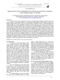
1 Replacing single -phase ACIMs with three -phase BLDC motors saves energy Sandun S. Kuruppu Systems Engineer John K. Rote Systems Engineer Manager Motor Drive Business Unit Texas Instruments A single -phase ACIM versus three -phase BLDC. motor efficiency comparison. single -phase and three -phase induction motors have been prominent in electromechanical energy conversion in industrial, residential and automotive applications. Advances in magnetic material technology have enabled alternative motor technologies such as brushless DC (BLDC) motors to emerge. This white paper compares permanent magnet-based, three -phase brushless DC machine-to-induction motor technologies in terms of efficiency. Electric motors are widely used in numerous exceed the torque of single -phase induction motors applications varying from appliances to power tools. of the same size. Motor selection for an application A significant amount of motor applications are found entails several criteria such as: in the form of fan applications such as: system efficiency bathroom exhaust fans inline fans system cost kitchen hood exhaust fans axial exhaust fans power quality appliance cooling fans attic ventilator fans acoustic performance dryer exhaust fans roof ventilation fans mechanical vibration and torque ripple desk fans radon fans product life Typical ventilation fans vary from 30W to 80W for Efficiency standards and residential applications.
2 Fan applications outside the residential segment can vary up to several kilowatts, requirements based on the application. Brushed DC motors, System efficiency being a key factor, efficiency single -phase AC induction motors, shaded-pole standards for motors are defined by regional induction motors, three -phase induction motors or governing bodies such as International three -phase brushless DC motors are some of the Electrotechnical Commission (IEC) in the European common motors available for fan applications. Our Union, and National Electrical Manufacturers analysis in this paper specifically relates to low- Association (NEMA) in the United States (US). power fan applications that include ventilation fans. Present IEC motors standards have four levels. These IEC 60034-30-1 efficiency classes are: Historically, single -phase induction motors dominated most low-power motor markets. At the 1. IE1 (standard efficiency). time, a key disadvantage was magnet technology.
3 2. IE2 (high efficiency). Ceramic magnets available at the time could not 3. IE3 (premium efficiency). deliver flux densities comparable to single -phase 4. IE4 (super premium efficiency). induction motors. Recent developments in magnet technology have enabled stronger magnets capable of producing torque levels that are equivalent to or Replacing 2 single -phase ACIMs with three -phase BLDC motors saves energy April 2016. These standards define the efficiency of 50 and The inverter stage shown in Figure 1 uses rectified 60 Hz motors with single - or three -phase windings line voltage to generate the DC bus voltage. built with any type of motor technology (brushless Efficiency of an electric machine is determined DC or induction, and so on) with power output based on the actual work done for the given input higher than 120W. power. Losses that occur in a motor are directly NEMA provides guidelines in the US for motor related to motor efficiency. Losses in an electric efficiency standards, which are: machine can occur in several forms which include: Old Standard Efficiency Motor copper loss Prior NEMA EE - stator copper loss (PCu,St ).
4 NEMA Energy - rotor copper loss (PCu,Ro ). NEMA Premium core loss (iron loss, PFe ). - hysteresis loss Similar to IEC standards, NEMA requirements for efficiency increase with higher output - eddy current loss our analysis, the assumption is that each motor is friction loss (PFr ). optimized for a specific application and each system windage loss (PWIND ). is controlled by a power converter that drives the Copper loss is also known as I2R loss and is caused motor. three -phase motors are controlled by a by the resistance in any current path. Due to pulse- three -phase inverter stage (Figure 1), and the start/ width modulation (PWM) switching, the winding's run capacitor single -phase induction motor' is effective resistance is increased. This phenomenon controlled by a by a three terminal semiconductor is caused by skin effect. The change in winding (TRIAC) (Figure 3). Alternate single -phase induction resistance due to skin effect is neglected in the motor drive methods include a transformer with analysis presented in this paper.
5 Hysteresis loss is several taps to control the average voltage applied, related to the characteristic of the material used in or using capacitors of different sizes in series with the stator and rotor material where the magnetic the auxiliary winding. flux cycles. The material's B-H loop area is directly related to the energy lost during energy conversion. Alternating magnetic fields in a conductor cause eddy currents (for example, in the motor material). The Circular electric currents that flow in the material contribute towards machine losses. Machine designers tend to use laminated material to reduce losses due to eddy currents. Figure 1: Drive stage for three -phase systems Loss characteristics vary based on motor type and design. The following sections address loss models Typical control strategy of BLDC motors in of three main motor technologies, followed by ventilation fan applications include position case studies that compare losses in a single -phase sensorless open-loop control or hall sensor-based induction motor and a three -phase BLDC.
6 Open-loop control as speed regulation is not a requirement in most cases. Replacing 3 single -phase ACIMs with three -phase BLDC motors saves energy April 2016. single -phase induction motors The phase shift between currents in the main and auxiliary windings results in a rotating magnetic field single -phase induction motors are widely used in in the air gap, which induces currents in the rotor various applications due to their simple design, low causing a rotor magnetic field enabling cost and simple control scheme. A motor cross torque generation. section of a single -phase induction motor is shown in Figure 2. The motor consists of a stator and a The equivalent circuit for the single -phase induction rotor. The rotor consists of a mechanical assembly motor (SPIM) (Figure 4, Figure 5) is based on known as a squirrel cage' in most designs, and the double revolving magnetic field theory with the stator consists of two windings. The main iron losses. Both windings in the SPIM contribute and auxiliary windings on the stator are spatially towards two magnetic fields in the air gap.
7 While displaced by 90 degrees. The auxiliary winding has one magnetic field moves in the forward direction, a capacitor in series with it (Figure 3). The capacitor the other moves in the opposite direction. Hence, allows the current in the auxiliary winding to be the equivalent circuit model of each winding approximately 90 degrees out-of-phase from the consists of a forward and a reverse component. current in the main winding. Figure 2: single -phase induction motor example cross section Figure 3: Capacitor start/run single -phase induction motor drive [1]. Figure 4: Equivalent circuit model for a SPIM [3]. Replacing 4 single -phase ACIMs with three -phase BLDC motors saves energy April 2016. Figure 5: Equivalent circuit for SPIM forward (a) and backward (b) components [3]. As these magnetic fields rotate in opposite Iron loss (PFe) in the motor is calculated as: directions they cause higher torque ripple, (9). resulting in vibration and noise in SPIMs. Typically, Where, the auxiliary winding and the main winding are connected in parallel to each other (equations 1-6): The mechanical output power (Pm) is calculated as: (1).
8 (10). (2). Friction and windage loss in a motor drive system (3). are represented as: (4) (11). (5). Unlike a permanent magnet synchronous machine (6) (PMSM), losses exist in the induction motor's rotor as well as the stator, regardless of the number of Na is the number of turns in the auxiliary winding, phases . Figure 6 shows the flow of losses. The and Nm is number of turns in the main winding. friction loss component is TFr and the windage Copper loss in the stator (PCu,St) is calculated as: loss is B. (7). Electrical Power Copper loss in the rotor (PCu,R) is calculated as: Power In Out (8). Figure 6: Losses in a single -phase induction motor [02]. Replacing 5 single -phase ACIMs with three -phase BLDC motors saves energy April 2016. Motor efficiency is quantified as (12 - 14): (12). (13). (14). The mechanical torque output is TMech, and the mechanical speed is Mech. Figure 7: Example three -phase ACIM cross-section Loss factors in three -phase IMs three -phase ACIMs are the work horse of the industry.
9 Low maintenance, inexpensive design, variable-speed capability, and relatively high efficiency make the three -phase induction motor (IM) an ideal candidate for process automation. three -phase IMs are cost-effective in high power applications at current material market prices. Figure 8: Per-phase equivalent circuit for a three -phase three -phase IM variable-speed operation is induction motor [7]. achieved via an inverter stage. Typically, these inverters are equipped with soft starters and power known as asynchronous machines because of the factor correction (PFC) stages to maintain line difference in the rotor and stator MMF speeds. power quality. Rotating MMF speed is a function of the stator A three -phase ACIM cross section is shown in winding current frequency. Now a variable frequency Figure 7. The equivalent circuit model is shown drive is able to control the motor speed by varying (per phase) in Figure 8. Similar to a single -phase the electrical frequency of the applied voltage.
10 In the IM, the three -phase IM also has stator and rotor case of a speed control application, the mechanical windings. Generally, the rotor is made up of a cast speed can be approximated only by knowing squirrel cage' type structure. Additionally, the the electrical frequency due to slip. An additional energy conversion principal of a three -phase ACIM speed sensor is necessary for an induction motor, if is similar to a SPIM. The three -phase ACIM stator accurate speed regulation is required. consists of a winding arrangement that generates a Losses that occur in a three -phase induction motor rotating magnetomotive force (MMF), when three - are approximated based on the equivalent circuit phase voltages are supplied to the motor. The result model (equations 15-17): is a rotating MMF that generates the rotor field, Air gap power: similar to single -phase induction motor. (15). Rotor MMF frequency is slightly less than stator MMF speed. This difference in speed is necessary Stator copper loss: to induce a magnetic field in the rotor.