Transcription of Single-Chip Low Cost Low Power RF-Transceiver …
1 CC1100 SWRS038D Page 1 of 92 CC1100 Low- Power Sub- 1 GHz RF Transceiver Applications Ultra low- Power wireless applications operating in the 315/433/868/915 MHz ISM/SRD bands Wireless alarm and security systems Industrial monitoring and control Wireless sensor networks AMR Automatic Meter Reading Home and building automation Product DescriptionThe CC1100 is a low- cost sub- 1 GHz transceiver designed for very low- Power wireless applications. The circuit is mainly intended for the ISM (Industrial, Scientific and Medical) and SRD (Short Range Device) frequency bands at 315, 433, 868, and 915 MHz, but can easily be programmed for operation at other frequencies in the 300-348 MHz, 400-464 MHz and 800-928 MHz bands.
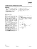
2 The RF transceiver is integrated with a highly configurable baseband modem. The modem supports various modulation formats and has a configurable data up to 500 kBaud. CC1100 provides extensive hardware support for packet handling, data buffering, burst transmissions, clear channel assessment, link quality indication, and wake-on-radio. The main operating parameters and the 64-byte transmit/receive FIFOs of CC1100 can be controlled via an SPI interface. In a typical system, the CC1100 will be used together with a microcontroller and a few additional passive components. 6789102019181716123451514131211CC1100 This product shall not be used in any of the following products or systems without prior express written permission from Texas Instruments: (i) implantable cardiac rhythm management systems, including without limitation pacemakers, defibrillators and cardiac resynchronization devices, (ii) external cardiac rhythm management systems that communicate directly with one or more implantable medical devices; or (iii) other devices used to monitor or treat cardiac function, including without limitation pressure sensors, biochemical sensors and neurostimulators.
3 Please contact if your application might fall within the category described above. CC1100 SWRS038D Page 2 of 92 Key FeaturesRF Performance High sensitivity ( 111 dBm at kBaud, 868 MHz, 1% packet error rate) Low current consumption ( mA in RX, kBaud, 868 MHz) Programmable output Power up to +10 dBm for all supported frequencies Excellent receiver selectivity and blocking performance Programmable data rate from to 500 kBaud Frequency bands: 300-348 MHz, 400-464 MHz and 800-928 MHz Analog Features 2-FSK, GFSK, and MSK supported as well as OOK and flexible ASK shaping Suitable for frequency hopping systems due to a fast settling frequency synthesizer: 90us settling time Automatic Frequency Compensation (AFC) can be used to align the frequency synthesizer to the received centre frequency Integrated analog temperature sensor Digital Features Flexible support for packet oriented systems: On- chip support for sync word detection, address check, flexible packet length, and automatic CRC handling Efficient SPI interface.
4 All registers can be programmed with one burst transfer Digital RSSI output Programmable channel filter bandwidth Programmable Carrier Sense (CS) indicator Programmable Preamble Quality Indicator (PQI) for improved protection against false sync word detection in random noise Support for automatic Clear Channel Assessment (CCA) before transmitting (for listen-before-talk systems) Support for per-package Link Quality Indication (LQI) Optional automatic whitening and de-whitening of data Low- Power Features 400nA SLEEP mode current consumption Fast startup time: 240us from sleep to RX or TX mode (measured on EM reference design [5] and [6]) Wake-on-radio functionality for automatic low- Power RX polling Separate 64-byte RX and TX data FIFOs (enables burst mode data transmission) General Few external components: Completely on- chip frequency synthesizer, no external filters or RF switch needed Green package: RoHS compliant and no antimony or bromine Small size (QLP 4x4 mm package, 20 pins) Suited for systems targeting compliance with EN 300 220 (Europe) and FCC CFR Part 15 (US).
5 Support for asynchronous and synchronous serial receive/transmit mode for backwards compatibility with existing radio communication protocols CC1100 SWRS038D Page 3 of 92 Abbreviations Abbreviations used in this data sheet are described below. ACP Adjacent Channel Power MSK Minimum Shift Keying ADC Analog to Digital Converter N/A Not Applicable AFC Automatic Frequency Compensation NRZ Non Return to Zero (Coding) AGC Automatic Gain Control OOK On-Off Keying AMR Automatic Meter Reading PA Power Amplifier ASK Amplitude Shift Keying PCB Printed Circuit Board BER Bit Error Rate PD Power Down BT Bandwidth-Time product PER Packet Error Rate CCA Clear Channel Assessment PLL Phase Locked Loop CFR Code of Federal Regulations POR Power -On Reset CRC Cyclic Redundancy Check PQI Preamble Quality Indicator CS Carrier Sense PQT Preamble Quality Threshold CW Continuous Wave (Unmodulated Carrier)
6 PTAT Proportional To Absolute Temperature DC Direct Current QLP Quad Leadless Package DVGA Digital Variable Gain Amplifier QPSK Quadrature Phase Shift Keying ESR Equivalent Series Resistance RC Resistor-Capacitor FCC Federal Communications Commission RF Radio Frequency FEC Forward Error Correction RSSI Received Signal Strength Indicator FIFO First-In-First-Out RX Receive, Receive Mode FHSS Frequency Hopping Spread Spectrum SAW Surface Aqustic Wave 2-FSK Binary Frequency Shift Keying SMD Surface Mount Device GFSK Gaussian shaped Frequency Shift Keying SNR Signal to Noise Ratio IF Intermediate Frequency SPI Serial Peripheral Interface I/Q In-Phase/Quadrature SRD Short Range Devices ISM Industrial, Scientific, Medical TBD To Be Defined LC Inductor-Capacitor T/R Transmit/Receive LNA Low Noise Amplifier TX Transmit, Transmit Mode LO Local Oscillator UHF Ultra High frequency LSB Least Significant Bit VCO Voltage Controlled Oscillator LQI Link Quality Indicator WOR Wake on Radio, Low Power polling MCU Microcontroller Unit XOSC Crystal Oscillator MSB Most Significant Bit XTAL Crystal CC1100 SWRS038D Page 4 of 92 Table Of Contents APPLICATIONS.
7 1 PRODUCT 1 KEY FEATURES .. 2 RF PERFORMANCE .. 2 ANALOG FEATURES .. 2 DIGITAL 2 LOW- Power 2 GENERAL .. 2 3 TABLE OF CONTENTS .. 4 1 ABSOLUTE MAXIMUM RATINGS .. 7 2 OPERATING CONDITIONS .. 7 3 GENERAL 4 ELECTRICAL SPECIFICATIONS ..8 CURRENT 8 RF RECEIVE 9 RF TRANSMIT 13 CRYSTAL 14 LOW Power RC 15 FREQUENCY SYNTHESIZER 15 ANALOG TEMPERATURE 16 DC 16 Power -ON 16 5 PIN 17 6 CIRCUIT DESCRIPTION .. 18 7 APPLICATION CIRCUIT .. 19 8 CONFIGURATION OVERVIEW .. 22 9 CONFIGURATION 24 10 4-WIRE SERIAL CONFIGURATION AND DATA INTERFACE .. 24 chip STATUS 26 REGISTER 26 SPI 27 COMMAND 27 FIFO 27 PATABLE 28 11 MICROCONTROLLER INTERFACE AND PIN CONFIGURATION .. 28 CONFIGURATION 28 GENERAL CONTROL AND STATUS 28 OPTIONAL RADIO CONTROL 29 12 DATA RATE 13 RECEIVER CHANNEL FILTER BANDWIDTH .. 30 14 DEMODULATOR, SYMBOL SYNCHRONIZER, AND DATA 30 FREQUENCY OFFSET 30 BIT 30 BYTE 31 15 PACKET HANDLING HARDWARE SUPPORT.
8 31 DATA 31 PACKET 32 PACKET FILTERING IN RECEIVE 34 PACKET HANDLING IN TRANSMIT 34 PACKET HANDLING IN RECEIVE 35 CC1100 SWRS038D Page 5 of 92 PACKET HANDLING IN 35 16 MODULATION FORMATS .. 36 FREQUENCY SHIFT 36 MINIMUM SHIFT 36 AMPLITUDE 36 17 RECEIVED SIGNAL QUALIFIERS AND LINK QUALITY INFORMATION .. 37 SYNC WORD 37 PREAMBLE QUALITY THRESHOLD (PQT) .. 37 37 CARRIER SENSE (CS).. 39 CLEAR CHANNEL ASSESSMENT (CCA) .. 40 LINK QUALITY INDICATOR (LQI) .. 40 18 FORWARD ERROR CORRECTION WITH INTERLEAVING .. 40 FORWARD ERROR CORRECTION (FEC).. 40 41 19 RADIO 42 Power -ON START-UP 42 CRYSTAL 43 VOLTAGE REGULATOR 43 ACTIVE 44 WAKE ON RADIO (WOR)..44 45 RX TERMINATION 46 20 DATA FIFO .. 46 21 FREQUENCY 48 22 VCO .. 48 VCO AND PLL 48 23 VOLTAGE REGULATORS .. 49 24 OUTPUT Power PROGRAMMING .. 49 25 SHAPING AND PA 50 26 SELECTIVITY.
9 52 27 CRYSTAL 53 REFERENCE 54 28 EXTERNAL RF MATCH .. 54 29 PCB LAYOUT 54 30 GENERAL PURPOSE / TEST OUTPUT CONTROL PINS .. 55 31 ASYNCHRONOUS AND SYNCHRONOUS SERIAL OPERATION .. 57 ASYNCHRONOUS 57 SYNCHRONOUS SERIAL 57 32 SYSTEM CONSIDERATIONS AND GUIDELINES .. 57 SRD 57 FREQUENCY HOPPING AND MULTI-CHANNEL 58 WIDEBAND MODULATION NOT USING SPREAD 58 DATA BURST 58 CONTINUOUS 59 CRYSTAL DRIFT 59 SPECTRUM EFFICIENT 59 LOW cost 59 BATTERY OPERATED 59 INCREASING OUTPUT 59 33 CONFIGURATION CONFIGURATION REGISTER DETAILS REGISTERS WITH PRESERVED VALUES IN SLEEP 64 CONFIGURATION REGISTER DETAILS REGISTERS THAT LOSE PROGRAMMING IN SLEEP 84 STATUS REGISTER 85 CC1100 SWRS038D Page 6 of 92 34 PACKAGE DESCRIPTION (QLP 20) .. 88 RECOMMENDED PCB LAYOUT FOR PACKAGE (QLP 20) .. 88 SOLDERING 88 35 ORDERING 89 36 REFERENCES.
10 90 37 GENERAL INFORMATION .. 91 DOCUMENT CC1100 SWRS038D Page 7 of 92 1 Absolute Maximum Ratings Under no circumstances must the absolute maximum ratings given in Table 1 be violated. Stress exceeding one or more of the limiting values may cause permanent damage to the device. Caution! ESD sensitive device. Precaution should be used when handling the device in order to prevent permanent damage. Parameter Min Max Units Condition Supply voltage V All supply pins must have the same voltage Voltage on any digital pin VDD+ max V Voltage on the pins RF_P, RF_N, and DCOUPL V Voltage ramp-up rate 120 kV/ s Input RF level +10 dBm Storage temperature range 50 150 C Solder reflow temperature 260 C According to IPC/JEDEC J-STD-020C ESD <500 V According to JEDEC STD 22, method A114, Human Body Model Table 1: Absolute Maximum Ratings 2 Operating Conditions The operating conditions for CC1100 are listed Table 2 in below.