Transcription of SOI-CMOS Device Technology - OKI
1 54 Special Edition on 21st Century SolutionsSpecial Edition on 21st Century SolutionsSOI- cmos Device TechnologyYasuhiro FUKUDA*, Shuji ITO**, Masahiro ITO**AbstractIn recent years, the mobile communication market represented by the mobile telephone has been showing remarkablegrowth. This market has been making tough demands for semiconductor integrated circuits, which are mountedcomponents, to consume less power, have higher integration, have multi-function capability, and be faster. We at Okihave been working on developing complete depletion type SOI devices in order to meet these needs.
2 We have alreadyimplemented m and m SOI-CMOS devices1. This article explains SOI-CMOS Device Technology anddiscusses current developments.* Silicon Solutions Company, VLSI R&D Center, Advanced VLSI Device /Process R& , General Manager** Silicon Solutions Company, VLSI R&D Center, AdvancedVLSI Device /Process R& , SOI Circuit R&D Team-2, Team LeaderSOI Device StructureThe term SOI means Silicon On Insulator structure, whichconsists of devices on silicon thin film (SOI layers) thatexists on insulating film.
3 Figure 1 illustrates an outlinesketch of bulk, partial depletion type and complete deple-tion type SOI-MOS (Metal Oxide Semiconductor) tran-sistor structure. In the case of bulk cmos devices , P/Ntype MOS transistors are isolated from the well layer. Incontrast, SOI-CMOS devices are separated into Si sup-porting substrate and buried oxide film (BOX). Also, thesedevices are structured so each element is completely iso-lated by LOCOS (Local Oxidation of Silicon) oxide filmand the operating elements area (called the SOI layer) iscompletely isolated by insulators.
4 Also, elements that havea thin SOI layer (normally <50 nm) and have all body areasunder the channel depleted, are called complete depletiontype SOI. Conversely, elements that have a thick SOI layer(normally >100 nm) and have some areas at the bottom ofthe body area that are not depleted, are called partialdepletion type of SOI-CMOS DevicesAs indicated below in Table 1, the S value that indicates thesub-threshold characteristics is unique in that only the Svalue of complete depletion type SOI transistors is the lowvalue of 60 - 70 mV/dec.
5 (The S value is the gate voltage atthe sub-threshold area that changes the drain current by onedigit with the drain voltage held constant.) Also, as illus-trated in Figure 1, the source, drain, substrate, and the PNjunction formed between wells in bulk transistors do notexist as complete depletion type transistors. Also, the junc-tion capacity is very small. Since a PN junction exists at thebottom of the body in partial depletion type transistors, itis located exactly between them. The advantages of the Svalue, reduced junction capacitance, and the totally iso-lated structure are as A low operating voltage is possible since the thresholdvoltage (Vt) can be set low without increasing the off-leak current.
6 (Reduced S value)2. Development of high-speed, low power consumptionCMOS devices is possible since the load capacitance CLis reduced. (Reduced junction capacitance)3. Reduced signal transmission loss during high-speedoperation. (Reduced junction capacitance)4. Realizing high-frequency component performance, in-cluding passive devices , is possible since high-resistanceSi wafers can be used as supporting substrates. (Totallyisolated structure)5. Reduced operation errors such as cross talk via thesubstrate.
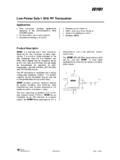
7 (Totally isolated structure)6. It is possible to prevent operation errors including latchup phenomena. (Totally isolated structure)N WellGateSource (P-)Drain (P-)Drain (P-)N-N-Source (P-)Drain (P-)Buried Oxide Film (BOX)Buried Oxide Film (BOX)Figure 1: Comparison Between Bulk cmos and SOI-CMOS StructuresGateSource (P-)LOCOS Oxide FilmSi Substrate (P type)Depletion LayerBulk cmos StructureGateGateLOCOS Oxide FilmLOCOS Oxide FilmBodyDepletion LayerDepletion LayerSi Supporting Substrate (P type)Partial Depletion Type SOI TransistorComplete Depletion Type SOI TransistorSi Supporting Substrate (P type)Body55 March 2001 OKI Technical Review 185 Vol.
8 687. Improved soft error durability by injecting radiation.(SOI layer thin film)Since we are considering expanding into the mobilecommunication market, we are aiming to develop one-chiplow power consumption cmos -LSI with combined analogand digital logic. We have therefore adopted completedepletion type SOI structure transistors as our develop-ment of low power consumption devices that use the low Svalue to make low power operation possible. On the otherhand, the following issues accompany complete isolation orthin-film SOI Source drain withstand voltage reduced by parasiticbipolar transistor operation (floating body potentialeffect due to complete isolation)2.
9 Increased transistor parasitic resistance (thin-film SOIlayer)3. Reduced tolerance to electrostatic discharge (ESD) (thin-film SOI layer)Next we would like to introduce the performance of m SIO- cmos devices we developed using complete depletiontype SIO structure transistors to overcome these issues andtake advantage of the previously mentioned m SOI-CMOS Device DevelopmentWe developed m SOI-CMOS devices by stipulating thepower supply voltage specifications to be V. In consider-ation of the complete depletion type transistor characteristicsand the current wafer variations, we specified 50 nm as theSOI layer thickness.
10 We decided to employ the Co (Cobalt)Silicide structure since we found that it is the most stablemeans of reducing transistor parasitic Figure 2illustrates the transistor sub-threshold characteristics. Thisfigure illustrates the characteristics of complete depletiontype SOI transistors when both P and N type MOS transistorshave a threshold voltage of V, and the S value becomes70 mV/dec. Photograph 1 shows a transistor cross-section. In this photograph, it is possible to confirm that the SOI layeris very thin by using the gate metal as a comparison.