Transcription of Solenoid directional valves DPHI DPHE - Atos
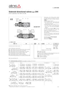
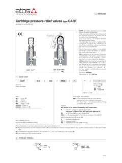
1 Table E085-7/E. Solenoid directional valves type DPHI and DPHE. two stage, ISO 4401 size 10, 16, 25 and 32. Spool type, two stage directional valves with solenoids certified according to North American standard cURus, available in two different executions: DPHI for AC and DC supply, Solenoid pilot type DHI, see tech. table E010. DPHE high performances, for AC and DC. supply, Solenoid pilot type DHE see tech. table E015. Single and double solenoids versions are available in two or three position configura- tions and with a wide range of interchan- geable spools , see section . Standard coils protection IP65. The valve body is made by shell-moulding casting with wide internal passages. The valves can be supplied with optional devices, see section for available options. DPHE-471*/H Mounting surface: ISO 4401, size 10, 16, 25 and 32. Max flow: 160, 300, 700, 1000 l/min. Max pressure: 350 bar 1 MODEL CODE.
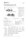
2 DPH E - 2 61 1 / A - X 24 DC ** / *. Seals material, Two stage directional control valve see section : Solenoid pilot valve: - = NBR. I = DHI for AC and DC supply with CURUS Series PE = FKM. certified solenoids number BT = HNBR. E = DHE for AC and DC supply, high performances with CURUS certified solenoids Voltage code, see section . Valve size: X = without connector 1 = 10 2 = 16 4 = 25 6 = 32 See section 14 for available connectors, to be orde- red separately 00 = Solenoid valve without coils (for DPHI). Valve configuration, see section . 61= single Solenoid , center plus external position, spring centered 00-AC = AC Solenoid valve without coils (for DPHE). 63= single Solenoid , 2 external positions, spring offset 00-DC = DC Solenoid valve without coils (for DPHE). 67= single Solenoid , center plus external position, spring offset 70= double Solenoid , 2 external positions, without springs 71= double Solenoid , 3 positions, spring centered Options, see note 1 at section.
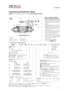
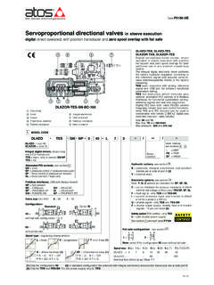
3 75= double Solenoid , 2 external positions, with detent Spool type, see section . 2 CONFIGURATIONS and SPOOLS (representation according to ISO 1219-1, for functional scheme, see section ). Configurations Spools Configurations Spools 1 0 2 1 0 2 1 0 2 1 0 2 1 0 2. 61. 63. 1 0. 0 1 2 3 1 2 0/2. 61/A. 0 2 4 5 6 7 63/A 1/2. 1 2. 67. 0 2 8 90 09 91 2/2. 70. 1 2 1 2. 19 93 39 94. 67/A. 1 0. 49 16 17 58 75. 71. 1 2. 1 0 2 NOTES (see also section 4,2 for special shaped spools): 1. 1 - For DP*-1 are available only spools: 0, 0/2, 1, 1/2, 3, 4, 5, 58, 6, 7. - For DP*-6 are available only spools: 0, 1, 1/2, 2, 3, 4, 5, 58, 6, 7, 8, 19, 91. E085. 1. 3 MAIN CHARACTERISTICS, SEALS AND HYDRAULIC FLUID - for other fluids not included in below table, consult our technical office Any position for all valves except for type -*70 (without springs) that must be installed with hori- Assembly position / location zontal axis if operated by impulses.
4 Subplate surface finishing Roughness index Ra 0,4 - flatness ratio 0,01/100 (ISO 1101). MTTFd values according to EN ISO 13849 75 years, for further details see technical table P007. Ambient temperature Standard execution = -30 C +70 C; /PE option = -20 C +70 C; /BT option = -40 C +70 C. NBR seals (standard) = -20 C +60 C, with HFC hydraulic fluids = -20 C +50 C. Seals, recommended fluid temperature FKM seals (/PE option)= -20 C +80 C. HNBR seals (/BT option)= -40 C +60 C, with HFC hydraulic fluids = -40 C +50 C. Recommended viscosity 15 100 mm2/s - max allowed range 500 mm2/s Fluid contamination class ISO 4406 class 21/19/16 NAS 1638 class 10, in line filters of 25 mm (b25 >. _ 75 recommended). Hydraulic fluid Suitable seals type Classification Ref. Standard Mineral oils NBR, FKM, HNBR HL, HLP, HLPD, HVLP, HVLPD DIN 51524. Flame resistant without water FKM HFDU, HFDR. ISO 12922.
5 Flame resistant with water NBR, HNBR HFC. Flow direction As shown in the symbols of table 2. P, A, B, X = 350 bar (for pilot pressure see also option /L9 at section ). T = 250 bar for external drain (standard). Operating pressure T and Y with internal drain (option /D) = 120 bar DPHI; 210 bar DPHE (DC); 160 bar DPHE (AC). Ports Y and L (if required): 0 bar Minimum pilot pressure for correct operation is 8 bar Rated flow See diagrams Q/Dp at section . Maximum flow DPH*-1: 160 l/min; DPH*-2: 300 l/min; DPH*-4: 700 l/min; DPH*-6: 1000 l/min (see rated flow at section and operating limits at section ). Coils characteristics Insulation class H (180 C) for DC coils (all versions) and AC coils (only DPHI). F (155 C) for AC coils (only DPHE). Due to the occuring surface temperatures of the Solenoid coils, the European standards EN ISO 13732-1 and EN ISO 4413 must be taken into account Protection degree to DIN EN 60529 IP 65 (with connectors 666, 667, 669 or E-SD correctly assembled).
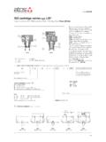
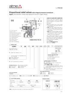
6 Relative duty factor 100%. Supply voltage and frequency See electric feature . Supply voltage tolerance 10%. Certification CURUS North American standard 4 NOTES. FUNCTIONAL SCHEME (config. 71). Options example of switching control options /A = Solenoid mounted at side of port A of main body (only for single Solenoid valves ). In standard version, Solenoid is mounted at side of port B. /D = Internal drain (standard configuration is external drain) 1 0 2. /E = External pilot pressure (standard configuration is internal pilot pressure). MAIN STAGE. /FV = With proximity switch for spool position monitoring: see tab. E110. option H, H9. /R = Pilot pressure generator (4 bar on port P - not for DPH*-1, see section 9 . option /S = Main spool stroke adjustment (not for DPH*-1). L1, L2, L3. /WP = Prolonged manual override protected by rubber cap. The manual override operation can be possible only if the pressure at T port is lower than 50 bar PILOT VALVE.)
7 Devices for main spool switching control and to reduce the hydraulic shocks at the valve operation /H = Adjustable chokes (meter-out to the pilot chambers of the main valve). /H9 = Adjustable chokes (meter-in to the pilot chambers of the main valve). /L1, /L2, /L3 = calibrated restrictors on A and B ports of the pilot valve: L1 =0,8mm, L2 =1mm, L3 =1,25mm). option L9. /L9 = (only for DP-2 and DP-4) plug with calibrated restictor in P port of pilot valve - see section 10. Suggested for pilot pressure higher than 210 bar or to limit the hydraulics shocks caused by the fast main spool switching Special shaped spools - spools type 0 and 3 are also available as 0/1 and 3/1 with restricted oil passages in central position, from user ports to tank. - spools type 1, 4, 5, 58, 6 and 7 are also available as 1/1, 4/8, 5/1, 58/1, 6/1 and 7/1 that are properly shaped to reduce water-hammer shocks during the switching (to use with option /L*).
8 Shaped spool availability 0/1 3/1 1/1 4/8 5/1 58/1 6/1 7/1. DPH*-1 . DPH*-2, DPH*-4 . DPH*-6 . 5 ELECTRIC FEATURES. Power Voltage External supply Type of consumption (3). Code of spare coil code Valve nominal voltage connec- Colour of coil label 10% tor DHI DHE DPHI DPHE. DPHI. 6 DC 6 DC (4) COU-6DC brown - 12 DC 12 DC COU-12DC green COE-12DC. 14 DC 14 DC COU-14DC brown COE-14DC. 24 DC 24 DC COU-24DC red COE-24DC. 28 DC 28 DC 33 W 30 W COU-28DC silver COE-28DC. 48 DC 48 DC COU-48DC silver COE-48DC. 110 DC 110 DC COU-110DC gold COE-110DC. 125 DC 125 DC COU-125DC blue COE-125DC. 220 DC. 666. 220 DC COU-220DC black COE-220DC. 24/50/60 AC. or 24/50 AC. DPHI (4) 667 COI-24/50/60AC (1) pink - 24/60 AC. 48/50/60 AC. - DPHE 48/50 AC 60 VA. (4) COI-48/50/60AC (1) white - 48/60 AC. 110/50 AC 110/50/60 AC 58 VA COI-110/50/60AC (1) yellow COE-110/50/60AC. 115/60 AC (5) 115/60 AC - 80 VA - COE-115/60AC.
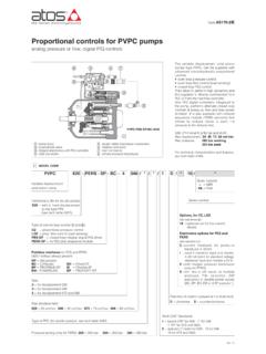
9 120/60 AC (4) 120/60 AC - COI-120/60AC white - 230/50 AC 230/50/60 AC 60 VA 58 VA COI-230/50/60AC (1) light blue COE-230/50/60AC. 230/60 AC 230/60 AC 80 VA COI-230/60AC silver COE-230/60AC. 110/50 AC 110RC COU-110RC gold COE-110RC. 120/60 AC. 669 33 W 30 W. 230/50 AC 230RC COU-230RC blue COE-230RC. 230/60 AC. (1) Coil can be supplied also with 60 Hz of voltage frequency: in this case (3) When Solenoid is energized, the inrush current is approx 3 times the the performances are reduced by 10 15% and the power consumption holding current. Inrush current values correspond to a power con- is 55 VA (DPHI) and 58 VA (DPHE) sumption of about 150 VA. (2) Average values based on tests performed at nominal hydraulic condi- (4) Only for DPHI. tion and ambient/coil temperature of 20 C. (5) Only for DPHE. 6 FLOW VERSUS PRESSURE DIAGRAMS Based on mineral oil ISO VG 46 at 50 C. DPH*-1 F E DPH*-2 I DPH*-4 L I H G.
10 F. E. Valve pressure drop Dp [bar]. Valve pressure drop Dp [bar]. D. Valve pressure drop Dp [bar]. H. G. C D. F. B E C. A D. B. C. B A. A. Flow [l/min] Flow [l/min] Flow [l/min]. DPH*6. C. Valve pressure drop Dp [bar]. B. A. DPH*-2 DPH*-4. Flow Flow direction P A P B A T B T P T direction P A P B A T B T P T. Spool Spool type type 0/2, 1, 3, 6, 7, 8 A A C D - 1 B B B D - 1/1, 1/2, 7/1 B B D E - 1/1 D E E F - 0 A A D E C 1/2 E D B C - Flow [l/min]. DPH*-1. 0/1 A A D - - 0 D C D E F. Flow 2 A A - - - 0/1, 3/1, 5/1, 6, 7 D D D F - direction P A P B A T B T P T 2/2 B B - - - 0/2 D D D E - Spool 3/1 A A D D - 2 B B - - - type 4 C C H I F 2/2 E D - - - 0/2, 1/2 D E D C - 4/8 C C G I F 3 B B D F - 0 D E C C E 5 A B F H G 4 C C H L L. 1 A B D C - 5/1 A B D F - 5 A D D D H. 3, 6, 7 A B C C - 6/1 B B C E - 6/1 D E D F - 4, 4/8 B C D D - 09 A - - G - 7/1 D E F F - 5, 58 A E C C F 16 A C D F - 8 D D E F - 17 C A E F - 09 D - - F F.