Transcription of source transformations - Iowa State University
1 EE 201source transformations 1 Consider the two circuits below. In particular, look at the current and voltage of RL in each circuit. Using any of the techniques we seen so far, it is easy to find iRL and vRL for each transformationsInteresting: From the point of view of the resistor RL, the series combination of the voltage source and resistor RS gives the exact same result as the parallel combination of current source and resistor RP. + RSRL +vRLVSiRL5 V2 k!1 k!RPRL + mA1 k!2 k!vRL=RLRL+RSVS=1k 1k +2k (5V)= = mA, P = mWiRL=1RL1RL+1 RPIS=11k 11k +12k ( )= = V, P = mWEE 201source transformations 2 The series combination seems to behave identically to the parallel combination. This suggests that we may, in the right circumstances, replace one configuration for the other. Making this switch is known as a source transformation. VSRSISRPIS = VS/RSRP = RSISRPVSRSVS = ISRPRS = RPEE 201source transformations 3 These are perfectly viable substitutions.
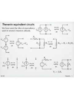
2 From the point of view of whatever circuitry is attached to the two terminals, the result will be exactly the same for the two source configurations. This is an example of bigger, more important idea known as the Thevenin equivalent of circuit. We will introduce this later, and make extensive use of it in discussing amplifiers, you are trying calculate something about the two components (VS-RS or IP-RP), you cannot transform them. In transforming them, you lose the ability to calculate a specific 201source transformations 425 50 200 100 50 V100 200 50 25 2 AThen use a current divider:Example 1 Find iR4 in the circuit at a source transformation to put everything in parallel. IS = VS/R1 = 50 V/25 ! = 2A.+ R1R2R3R4 VSiR4R1R2R3R4 ISiR4iR4=1R41R1+1R2+1R3+1R4IS=1100 125 +150 +1200 +1100 (2A)= 201source transformations 5 Example 2 Find iR2 in the circuit at k k 20 V2 mATransform the voltage source / resistor combo. IST = VS/R1 = 20 V/5 = 4 mA6 mACombine the two current sources, IP = IST + IS = 6 use the current divider then once again.
3 + VSISR1R2iR25 k k 2 mA5 k k R1R2 IPiR2iR2=1R21R1+1R2IP= +15k (6mA)= 201source transformations 6 Example 3VS+ ISR1R2iR1(An incorrect application)Find iR1 in the circuit at V1 k 1 k 15 mAThe previous example worked nicely so use the same method. Transform VS & R1, and use current divider with the total = 5 5 + 5 (,67+,6)40 mA1 k 1 k 15 mA= N N + N ( P$)= . P$It seems nice, but it is wrong because you cannot transform the component for which you are trying to find voltage or current. (To see that it is wrong, insert iR1 = mA in the original circuit and show that there are serious inconsistencies with the currents and voltages.)EE 201source transformations 7 Example 3(Redo it correctly.)VS+ ISR1R2iR1 Find iR1 in the circuit at IS & + R1R2iR1 VST+ 40 V1 k 1 k 15 mA40 V1 k 1 k 15 VWriting a KVL loop equation and solving for iR1 givesL5 =96 9675 +5 = 9 9 N + N = . P$This is the correct 201source transformations 8 Example 4VS1+ + VS2 ISR1R2R3R4R5 Find vR5 in the circuit at V5 36 A60 V20 6 8 vR5+ Transform two voltage sources to current sources.
4 (Pay attention to polarity.)ISIST1 IST2R1R2R3R4R536 A6 A12 A20 5 6 8 vR5+ EE 201source transformations 9 Example 4 (cont.)Add the parallel current sources into one. Combine the parallel resistors into 8 vR5+ Ieq = 6A 12 A + 36 A = 30 = 20 || 5 || 6 = .30 Transform Ieq & Req:+ VeqtReqR4R572 8 vR5+ Use voltage divider:Y5 =5 5HT+5 +5 9 HTW= . + . + ( 9)= 9