Transcription of SSI Synchronous Serial Interface Master - Application Note
1 AMERICA FRABA Inc. 1800 East State Street, Suite 148 Hamilton, NJ 08609-2020, USA T +1-609-750-8705, F +1-609-750-8703 , EUROPE POSITAL GmbH Carlswerkstrasse 13c D-51063 K ln, Germany T +49 221 96213-0, F +49 221 96213-20 , ASIA FRABA Pte. Kallang Avenue #01-00 Pico Creative Centre Singapore 339411, Singapore T +65 65148880, F +65 62711792 , IMPLEME NT AT ION OF SSI MAST ER I NT ERFA CE APPLICAT ION NO T E Application Note 12 August 2013 IMPLEME NT AT ION OF SSI MAST ER I NT ERFA CE APPLICAT ION NO T E 2013-11-08 2/26 10021488 For additional information about our products click on the links below: IXARC Rotary Encoders TILTIX Inclinometers LINARIX Linear Sensors Table of Contents IMPLEME NT AT ION OF SSI MAST ER I NT ERFA CE APPLICAT ION NO T E 2013-11-08 3/26 10021488 Table of Figures.
2 4 Introduction .. 5 1. SSI Theory .. 6 2. SSI Hardware .. 10 Simple SSI Master Implementation .. 10 SSI Interface with Opto-coupler (Galvanic Insulated) .. 11 Illustration of SSI Transfers using differential signals .. 12 3. SSI Software .. 13 SSI Interface Using I/O Ports .. 13 Reading SSI with the SPI Port .. 15 Evaluating the Data 16 Separating Singleturn and Multiturn values .. 17 Calculating an Angle from the Single Turn Value .. 19 Appendix a: Complete 21 Appendix B: References .. 26 History of Changes .. 26 IMPLEME NT AT ION OF SSI MAST ER I NT ERFA CE APPLICAT ION NO T E 2013-11-08 4/26 10021488 Table of Figures Figure : SSI Logo.
3 5 Figure : Simple SSI Block Diagram .. 6 Figure : SSI Timing Diagram .. 7 Figure : Multiple Transmissions in SSI Interface .. 8 Figure : Real World SSI Transfer .. 9 Figure : Simple SSI Master .. 10 Figure : SSI with Opto-coupler (Galvanic Insulated) .. 11 Figure : SSI transfer with differential signals .. 12 Figure : SSI transfer when encoder not connected .. 12 Figure : Code Example for Reading SSI Data by pin 13 Figure : Transmission with Pin Toggle .. 14 Figure : Code Example: Main routine contains delay .. 14 Figure : Code Example: Using the SPI to read SSI data .. 15 Figure : SSI transfer using SPI .. 16 Figure : Code Example : Extracting Multi Turn and Single Turn values.
4 17 Figure : Data Transfer (port toggling method) .. 17 Figure : Screenshot of Evaluation Result.. 18 Figure : Code Example: Extracting Multi Turn and Single Turn values .. 19 Figure : Screenshot with Angle Result .. 20 IMPLEME NT AT ION OF SSI MAST ER I NT ERFA CE APPLICAT ION NO T E 2013-11-08 5/26 10021488 Introduction Figure 1: SSI Logo This Application note describes in detail on how to implement a Synchronous Serial Interface (SSI) Master using an Atmel ATmega88 controller. The following sections will cover a brief description about the SSI protocol and discuss the hardware and software implementations in detail. For better understanding, hardware examples and illustrations of soft-ware implementation with I/O ports and SPI Interface of the ATmega 88 have been used.
5 Although, the knowledge of the ATmega88 is helpful for programming, it is not very necessary to under-stand the underlying concepts about the Synchronous Serial Interface implementation explained in this document. IMPLEME NT AT ION OF SSI MAST ER I NT ERFA CE APPLICAT ION NO T E 2013-11-08 6/26 10021488 1. SSI Theory Synchronous Serial Interface (SSI) is a widely used Serial Interface standard for industrial applications especially, rotary encoders. It is a point-to-point connection from a Master ( PLC, microcontroller or other control systems) to a slave ( the rotary encoder).
6 In this type of Interface , the position data is continually updated by the sensor and made available to the output register. Data is shifted out when the sensor receives a pulse train from the controller. When the least significant bit (LSB) is transmitted, the sensor holds the data constant for a certain period of time. When this time has elapsed, the new position data is updated to the output register continuously once again. The Clock (CLK) and Data (DTA) signals are transmitted according RS-422 standards. This standard also known as, TIA/EIA-422-B, is an industry standard specifying the electrical characteristics of a differential voltage driven transmission circuit.
7 The advantage of differential signalling is the improved resistance to electromagnetic interference (EMI), especially in industrial environments and on larger signal line (Transmission) lengths. SSI Data is transferred in a single data word with the most significant bit (MSB) first. Rotary encoders normally use 13 bits of data for transmitting the angle within one revolution (singleturn). If the revolutions are also counted (multiturn), a 25 bit word is used. Conventionally, the SSI Interface of the slave would have been implemented using a parallel load shift register in conjunction with a retriggerable mono flop to freeze the value, while a transfer is in progress.
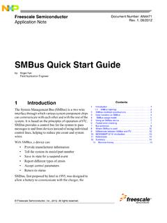
8 But nowadays, the Interface is commonly integrated into FPGAs, PLDs or customized ASICs. Master ( C) slave (Encoder) Data (DTA) Clock (CLK) Figure : SSI Basic Block Diagram Figure : Simple SSI Block Diagram IMPLEME NT AT ION OF SSI MAST ER I NT ERFA CE APPLICAT ION NO T E 2013-11-08 7/26 10021488 An ideal SSI timing diagram can be found below, in figure Figure : SSI Timing Diagram The time tm represents the transfer timeout. This is the time required by the encoder to recognize that a transfer is complete. tp is called the pause time or the time delay between two consecutive clock sequences. It should always be greater than 21 s, a maximum time is not defined.
9 In idle state, encoder data line stays HIGH. After the first falling edge of the clock, the the position value of the encoder is still held constant with the Data Level still remaining in HIGH With the first rising edge, the first bit, the MSB is transmitted each rising clock edge will trigger the transmit of a bit. Finally when the LSB is transferred (end of transmission) an additional rising clock will set the data output to LOW level. This will be held low for 20 1 s (monoflop time). After the time is over the encoder will start to update the position value continuously and the data line is set to HIGH state.
10 The next transmission is started with a train of clock pulses. The maximum clock frequency can be to 2 MHz or higher (period of 500ns). The minimum clock frequency is 50 KHz. This value is determined by the timeout definition. For example, a timeout time of 20 1 s corresponds to 50 KHz. Most SSI-devices implement multiple transmissions. Multiple transmission, also known as ringshift or double transmission, can be used to improve transfer safety by repeatedly reading the same data word. The encoder will not update the data word before SSI timeout occurs. If the encoder is continuously clocked, it leads to multiple transmissions of the same position data without updating.