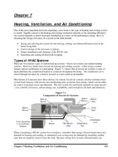
Transcription of Stand Alone PV System Sizing Worksheet (example)
1 Stand Alone PV System Sizing Worksheet ( example ) Application: Stand Alone camp System 7 miles off grid Location: Baton Rouge, La Latitude: N A. Loads A1 Inverter efficiency 85 A2 Battery Bus voltage 24 volts A3 Inverter ac voltage 110 volts A4 A5 A6 A7 A8 Adjustment Factor Adjusted Hours Energy Rated for dc Wattage per day per day Appliance Wattage (A1) for ac (A4/A5) Used (A6xA7) (5) 30w lights 150 .85 176 2 352 Refrigerator 500 .85 588 5 2940 (3) 45w fans 135.
2 85 159 8 1272 Washer 1500 .85 1765 .86 1518 Tv 200 .85 235 4 940 Toaster 1500 .85 1765 .025 441 A9 Total energy demand per day (sum of A8) 7463 watt-hours A10 Total amp-hour demand per day (A9/A2) 311 amp-hours A11 Maximum ac power requirement (sum of A4) 3985 watts A12 Maximum dc power requirement (sum of A6) 4688 watts B. Battery Sizing Design temperature 25 degrees C / 77 degrees F B1 Days of storage desired/required 7 days B2 Allowable depth-of-discharge limit (decimal) B3 Required battery capacity ((A10 x B1) / B2) 2721 amp-hours B4 Amp-Hour capacity of selected battery * 478 amp-hours B5 Number of batteries in parallel (B3 / B4) 6 B6 Number of batteries in series (A2 / selected battery voltage) 2 B7 Total Number of Batteries (B5xB6) 12 B8 Total battery amp-hour capacity (B5xB4)
3 2868 amp-hours B9 Total battery kilowatt-hour capacity ((B8xA2)/1000) Kw-hours B10 Average daily depth of discharge (.75xA10/B8) .08 *Use amp hour capacity at a rate of discharge corresponding to the total storage period B1 from battery spec sheet (B4). C. PV Array Sizing Design Tilt (Latitude + 15 degrees) Design month: December C1 Total energy demand per day (A9) 7463 watt-hours C2 Battery round trip efficiency ( ) C3 Required array output per day (C1 / C2) 8780 watt-hours C4 Selected PV module max power voltage at STC ( ) Volts C5 Selected PV module guaranteed power output at STC watts C6 Peek sum hours at design tilt for design month hours C7 Energy output per module per day (C5xC6) 181 watt-hours C8 Module energy output at operating temperature (DFxC7) DF = for hot climates and critical applications.
4 DF = for moderate climates and non-critical applications. 163 watt-hours C9 Number of modules required to meet energy requirements (C3 / C8) 54 modules C10 Number of modules required per string (A2 / C4) rounded to the next higher integer. 2 modules C11 Number of strings in parallel (C9 / C10) rounded to the next higher integer. 27 strings C12 Number of modules to be purchased (C10 x C11) 54 modules C13 Nominal rated PV module output 53 watts C13 Nominal rated array output (C13 x C12) 2862 watts D.
5 Balance-of- System (BOS) Requirements 1. A voltage regulator is recommended unless array output current (at 1000 W/m^2 conditions), less any continuous load current, is less than 5 % of the selected battery bank capacity (at the 8 hour discharge rate0). 2. Wiring should be adequate to ensure that losses are less than 1% of the energy produced. 3. In low voltage ( , less than 50 volts) systems, germanium or Schottky blocking diodes are preferred over silicon diodes. 4. Fuses, fuse holders, switches, and other components should be selected to satisfy both voltage and current requirements.
6 5. All battery series branches should contain fuses. 6. Fused disconnects are strongly recommended to isolate the battery bank from the rest of the System . 7. Refer to electrical and mechanical design sections for other considerations. APPLICATION: Stand - Alone camp System 7 miles off grid LOCATION: Baton Rouge, La LATITUDE: degrees N A. LOADS (A1): Inverter efficiency (decimal). This quantity is used as a power adjustment factor when current is changed from dc to ac. The efficiency of the inverter selected for this application is assumed to be (A2): Battery bus voltage.
7 This is nominal dc operating voltage of the System . The battery bus voltage for this application is 24 volts. Which corresponds to the required dc input voltage for the inverter. (A3): Inverter ac voltage. The output voltage of the inverter selected for this application is 110 volts. The components (appliances) that the System will power are: 5 lights (30w each0, combined rated wattage 150, used 2 hours/day. Refrigerator, rated wattage 500, used 5 hours/day. 3 ceiling fans (45w each0, combined rated wattage 135, used 8 hours/day. Washer, rated wattage, 1500, used 6 hours/week or hours/day.))
8 Television, rated wattage 200, used 4 hours/day. Toaster, rated wattage 1500, used hours/day. The appliances are listed under the column heading Appliance. LOADS (A4): The rated wattage is listed for each appliance in column (A4). Note that the rated wattage for some appliances may vary from the actual power consumed due to the load variation or cycling ( refrigeration, motors, etc.) (A4) Rated Appliance Wattage 5 lights (30w each) 150 Refrigerator 500 3 ceiling fans (45w each0 135 Washer 1500 Television 200 Toaster 1500 (A5): Adjustment factor.)
9 The adjustment factor is related to the efficiency of the inverter and reflects the actual power consumed from the battery bank to operate ac loads from the inverter. For ac loads, the value (A1) is inserted in column (A5). For this application the adjustment factor is For dc loads operating from the battery bank an adjustment factor of is used. (A6): Adjusted wattage. Dividing the rated wattage 9A4) by the adjustment factor (A5) adjusts the wattage to compensate for the inverter inefficiency and gives the actual wattage consumed from the battery bank (A4 / A5).
10 Adjusted Appliance (A4 / A5) = Wattage (A6) 5 lights (30w each) 150 / = 176 Refrigerator 500 / = 588 3 ceiling fans (45w each) 135 / = 159 Washer 1500 / = 1765 Television 200 / = 235 Toaster 1500 / = 1765 (A7): Hours per day used. The number of hours each appliance is used per day is listed in column (A7). The duty cycle, or actual time of load operation, must be considered here. For example , a refrigerator may be functional 24 hours a day, but the compressor may only operate 5 hours per day.