Transcription of STANDARD LOW EMISSION FORGED STEEL GATE, …
1 STANDARD LOW EMISSION . FORGED STEEL . gate , GLOBE AND CHECK VALVE. INSTALLATION, OPERATION & MAINTENANCE MANUAL. DECEMBER 2012. Bonney Forge Corporation 14496 Croghan Pike Mount Union, PA 17066. Installation, Operation & Maintenance Manual Table of Contents Introduction .. 1. Receiving, Handling, and Storage .. 1. Receiving and 2. Valve Storage .. 2. Valve Identification .. 3. 4. Preliminary Installation Considerations .. 4. Valve Connection Type .. 4. Valves Installed by Butt Weld or Socket Weld .. 5. Valves Installed by Threaded Connection .. 8. Valves Installed by Flanged End Connection .. 8. Valve Position .. 9. Positioning Check Valves in the Pipe Run .. 9. Positioning gate and Globe Valves in the Pipe Run .. 10. Purging and Testing of Line .. 10. Valve Operation .. 12. gate Valve .. 14. Globe Valve .. 15. Piston Check/Ball Check Valve .. 15. Swing Check 18. Maintenance .. 19. List of Tools for Maintenance and Repair .. 19. Preventative Maintenance.
2 19. Valve Lubrication .. 20. Points of 21. Recommended Stem and Yoke Sleeve Lubricants .. 22. Stem Packing (Eco-Seal ) .. 23. Maintenance Conditions for Fugitive emissions Performance .. 23. Stem Packing Bolting Torque .. 24. Stem Packing Repair .. 25. Body-Bonnet 27. Body-Bonnet Assembly .. 28. Gasket Replacement (Bolted Bonnet Valves Only).. 30. gate Valve Seating Surfaces: Repair and Replacement .. 30. Globe & Check Valve Seating Surfaces: Repair and Replacement .. 30. Seat Surface Repair .. 31. Seat Ring Replacement (Threaded) .. 33. Swing Check Valve Seating Surfaces: Repair and Replacement .. 33. Motor-Operated Valves .. 34. Spare Parts .. 36. Troubleshooting Guide .. 36. i Installation, Operation & Maintenance Manual Table of Figures Figure 1 - Weld Set Up .. 6. Figure 2 - Post Weld Heat Treatment .. 7. Figure 3 - Check Valve Positions .. 11. Figure 4 - gate and Globe Valve Positioning .. 12. Figure 5 - Typical gate Valve (Bolted Bonnet Design).
3 14. Figure 6 - Typical Globe Valve (Bolted Bonnet Design) .. 15. Figure 7 - Typical Piston/Ball Check Valve (Bolted Bonnet Design) .. 17. Figure 8 - Typical Swing Check Valve (Bolted Bonnet Design) .. 18. Figure 9 - gate and Globe Valve Points of Lubrication .. 21. Figure 10 - Extraction of Valve Packing .. 26. Figure 11 - Typical Low- EMISSION Replacement Packing Ring Configuration .. 26. Figure 12 - Body-Bonnet Bolt Torque Sequence .. 29. Figure 13 - Fixture for Globe & Piston/Ball Check Valve Seat Surface Repair .. 32. Figure 14 - Components of a Motor-Operated Valve .. 34. Figure 15 - Supporting a Motor-Operated Valve .. 35. Appendix A - Exploded View Typical gate Valve (Bolted Bonnet Design) .. 38. Appendix B - Exploded View Typical Globe Valve (Bolted Bonnet Design) .. 39. Appendix C - Exploded View Typical Piston/Ball Check Valve (Bolted Bonnet Design) .. 40. Appendix D - Exploded View Typical Swing Check Valve (Bolted Bonnet Design).
4 41. Appendix E Packing Styles By Figure Number and Valve Size .. 42. List of Tables Table 1 - Preventive Maintenance Schedule .. 20. Table 2 - Recommended Lubricants .. 23. Table 3 - Gland Bolt Torque (Low EMISSION Packing) .. 24. Table 4 Approved/Recommended Replacement Packing (Certified Low E Packing) .. 25. Table 5 - Body-Bonnet Bolt Torque Table .. 29. Table 6 - Troubleshooting Guide .. 36. ii Installation, Operation & Maintenance Manual This page is intentionally left blank iii Installation, Operation & Maintenance Manual Introduction Choosing the correct valve for a particular operation or service is very important; however, it is not within the scope of this document to provide information regarding valve selection. It is the intent of this manual to provide detailed information directed towards proper installation, operation, and maintenance of Bonney Forge FORGED STEEL valves. The types of valves discussed herein are: gate Valves: Used in the fully open or fully closed position for on-off service.
5 Globe Valves: Used for throttling control as well as on-off service. Self-Actuated Check Valves: Used to prevent backflow (fluid flow reversal). With proper care and regular maintenance, users can expect long life and excellent performance from all Bonney Forge valves. If major repairs become necessary, it is recommended that the valves be returned to the factory for inspection and possible rework. In addition to the installation, operation, and maintenance instructions provided herein, further guidance and information on these topics can be found in MSS SP-92, MSS Valve User Guide, published by the Manufacturer's Standardization Society (MSS). Information in this manual that was extracted from MSS SP-92 is indicated by a footnote. Receiving, Handling, and Storage Bonney Forge FORGED STEEL valves are packaged in a variety of manners: Cardboard boxes Cardboard boxes and palletized Wooden Containers The packing method depends on factors such as valve size/weight, purchase order quantities, and customer packing requirements.
6 All valves are carefully and securely packaged in a manner to prevent damage during shipment. gate and globe valves are shipped in the closed position. 1|P age Installation, Operation & Maintenance Manual Receiving and Handling Upon receipt of shipment, verify the integrity of the boxes or containers, examine external package markings, and verify the presence of a packing list. Open boxes or remove the container lid using suitable hand tools. Check contents for valve type, size, class, material, and quantity against the packing list. Inspect the condition of all valves for shipping damage. If the end protectors have been removed for inspection purposes, they must be re-installed to maintain internal cleanliness. If the caps are missing, an inspection of the valve cavity is required. Foreign material must be removed. Valves should not be opened when cleaning prior to removal of foreign material. If cleaning of the valve is required, care must be taken as to the type of solvents used, particularly if the valve is to be connected to the line by welding.
7 Solvents such as acetone or alcohol are recommended. Do not use solvents containing fluoride or chloride. Additionally, care must be taken to prevent damage to seating surfaces during cleaning. Removal of foreign material from the valve and areas around the seats is critical. Any foreign material that cannot be removed around or on the seating areas may require the valves to be disassembled and repaired at a Bonney Forge approved modification shop. Care shall also be taken in the proper handling of valves to prevent damage. Valves should never be thrown or dropped. Lifting the valve by the stem is not advisable and, for larger valves, lifting the valve by the hand wheel or the packing gland flange is not recommended. Valve Storage All Bonney Forge carbon STEEL and alloy STEEL FORGED valves are shipped from the factory with a phosphate coating on un-machined surfaces and with a rust preventative sprayed on machined surfaces. In addition, plastic end protectors are installed on both end connections for protection from damage and to prevent entrance of foreign materials into the valve.
8 Valves received in the above condition and in their original shipping containers may be stored for up to one year with no additional protection; provided they are stored indoors, above floor level, and in a low humidity atmosphere. If the valves are removed from their original shipping containers, they should be placed above floor level on suitable storage shelves. If valves are to be stored indoors for a longer period of time in a high humidity atmosphere, it is suggested that each item be periodically inspected, inside and out, for rust and/or corrosion. 2|P age Installation, Operation & Maintenance Manual The valves should be cycled open and closed, during which time each valve stem should be inspected for corrosion. Any external rust and/or corrosion should be removed by cleaning the affected area with a wire brush followed by the application of a suitable rust preventative. Valve Identification Each Bonney Forge valve is identified with a nameplate, which is placed over the hand wheel and secured with the hand wheel nut on gate and globe valves, and riveted to the cover on check valves.
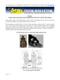
9 Below are (2) examples of Bonney Forge nameplates, the nameplates differ depending on where the valve was manufactured. 1. NACE marking indicating the valve is in compliance with NACE MR0103 & MR0175. 2. Applicable Design Codes. 3. Bonney Forge Valve Figure Number 4. Shell Material ( Body, Bonnet). 5. Stem Material 6. Closure Member Material (In case of hard face overlay, HF will be marked.). 7. Seat Material (In case of hard face overlay, HF will be marked.). 8. Rated Pressure Class 9. Valve Type 10. Nominal Pipe Size 11. Maximum Working Pressure (PSI) at Reference Ambient Temperature per ASME 12. Reference Ambient Temperature per ASME 13. CE Marking which complies with the requirements of European Pressure Equipment Directive 97/23/EC. 3|P age Installation, Operation & Maintenance Manual Installation Preliminary Installation Considerations Bonney Forge Valves are tested and shipped ready for installation. Prior to installation, consideration shall be given to the following: Only experienced, trained personnel should install, operate, and perform maintenance on all valves.
10 Observe all State and Local Codes as well as National standards and Safety Procedures that pertain to the installation of all valves. Always use tools to the intent for which they were designed, to prevent damage to the valve, and to prevent injury or death to the user. Examine valve nameplate and tags to ensure the correct valve is being installed. Remove all end protectors. Inspect the inside of the valve for cleanliness through the valve end ports. Remove any debris or foreign material. See Section Consult flow arrows marked on valve body for proper installation. Packing stud bolt nuts must be tightened to the correct torque shown in Table 3 prior to operation. Packing gland bolts may loosen during shipment. Installing a valve with loose packing nuts can result in packing leakage. Valve Connection Type Depending on valve end configuration, three (3) basic installation procedures are used: Welded Connection: Socket Weld - In accordance with ASME 1.
