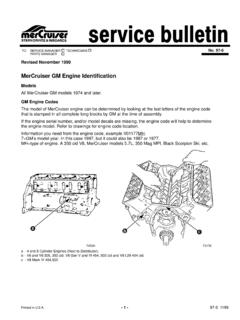
Transcription of STEERING SYSTEM - boatfix.com
1 STEERING SYSTEM . 6. A. 22147. POWER STEERING . Index Table of Contents Page Page Specifications .. 6A-1 Cable Guide Tube .. 6A-18. Torque Specification .. 6A-1 Removal .. 6A-18. Special Tools .. 6A-1 Installation .. 6A-19. Lubricants/Sealers/Adhesives .. 6A-1 Control Valve .. 6A-20. Description .. 6A-1 Removal .. 6A-20. Power STEERING SYSTEM .. 6A-2 Disassembly .. 6A-20. Power STEERING SYSTEM .. 6A-3 Reassembly ..6A-22. Power STEERING SYSTEM .. 6A-4 Installation .. 6A-25. STEERING Helm and Cable .. 6A-5 Booster Cylinder .. 6A-26. Power STEERING Models .. 6A-5 Removal .. 6A-26. Filling and Air Bleeding Power STEERING Installation .. 6A-27. SYSTEM .. 6A-6 Power STEERING Pump .. 6A-29. Balancing Power STEERING Control Valve .. 6A-7 Removal .. 6A-29. Power STEERING Drive Belt Inspection .. 6A-9 Flow Control Valve Servicing .. 6A-29. STEERING Cable Selection, Removal and Pump Shaft Oil Seal Replacement .. 6A-29. Installation .. 6A-9 Disassembly .. 6A-31. Selection.
2 6A-9 Cleaning And Inspection .. 6A-32. Removal .. 6A-10 Reassembly ..6A-32. Installation .. 6A-10 Installation .. 6A-35. Testing Power STEERING SYSTEM .. 6A-11 Determining Tie Bar Length .. 6A-36. Test Gauge Assembly .. 6A-11 Selection .. 6A-36. Power STEERING Pump Lugging Test .. 6A-11 Installation .. 6A-37. Power STEERING SYSTEM Pressure Test .. 6A-12 Dual Installations With STEERING Cable Pump Pressure Test .. 6A-14 Attached To Starboard Power Booster Cylinder Test .. 6A-15 Package .. 6A-37. Power STEERING Component Repair .. 6A-16 Dual Installations With STEERING Cable Power STEERING Unit .. 6A-16 Attached To Port Power Package .. 6A-38. Removal .. 6A-16. Installation .. 6A-16. Index 6A-0 - STEERING SYSTEM 90-12934--2 1097. Specifications Description The Power STEERING SYSTEM utilizes an engine-driv- Torque Specification en, vane-type hydraulic pump that supplies fluid flow and pressure by means of hoses to a control valve TORQUE that, in turn, controls fluid flow and pressure to-and- DESCRIPTION.
3 Lb. in. lb. ft. N m from a booster cylinder. Three modes make up the Coupler Nut 35 48 basic function of the Power STEERING SYSTEM : 1) neu- tral mode, 2) left-turn mode, and 3) right-turn mode. Pivot Bolts 25 35 The control valve, which is activated by the STEERING Power STEERING Hose cable, controls the STEERING SYSTEM modes. 20-25 27-34. (Large Fitting). NOTE: The following Power STEERING unit installa- Power STEERING Hose 96-108 11-12 tions are viewed from inside boat , looking at transom. (Small Fitting). STEERING Tube Nut 15-20 20-27. Control Valve Screw 25-35 34-47. Power STEERING Fitting 35 47. Assembly Special Tools Description Part No. Power STEERING Test Gauge 91-38053A3. Power STEERING Pump Pulley 91-93656A1. Installer KENT-MOORE SPECIAL TOOLS. Can be ordered from: Kent-Moore Tools, Inc. 29784 Little Mack Roseville, MI 48066. Phone: 313-774-9500. Power STEERING Pump Kent-Moore Part Pulley Remover No. J-25034-C. Lubricants/Sealers/. Adhesives Description Part No.
4 2-4-C Marine Lubricant 92-825407A2. Special Lubricant 101 92-13872A1. Locquic Primer T 92-59327-1. Loctite No. 35 92-59328-1. Loctite Type A Obtain Locally Index 90-12934--2 1097 STEERING SYSTEM - 6A-1. Power STEERING SYSTEM (VIEWING FROM INSIDE OF boat LOOKING AT. TRANSOM). 22213. Index 6A-2 - STEERING SYSTEM 90-12934--2 1097. Power STEERING SYSTEM (VIEWING FROM INSIDE OF boat LOOKING AT. TRANSOM). 22215. Index 90-12934--2 1097 STEERING SYSTEM - 6A-3. Power STEERING SYSTEM (VIEWING FROM INSIDE OF boat LOOKING AT. TRANSOM). 22214. Index 6A-4 - STEERING SYSTEM 90-12934--2 1097. STEERING Helm and Cable Power STEERING Models Transom assembly is shipped with the STEERING cable guide tube preset for cables with end dimensions that comply with ABYC standards as outlined in the NMMA certification handbook. The STEERING cable coupler nut must also have a means of locking it to the guide tube, as specified in ABYC requirements. ! WARNING. Failure to use a STEERING cable locking device could cause loss of STEERING , which could cause damage to the boat and/or injury.
5 50629. All current production Quicksilver Ride Guide steer- a - Locking Plate 92766. ing cables have a self-locking coupler nut and do not b - Screw 10-41209-(See Torque Specifications ). require an external locking device. (Other cable c - Washer 12-35462. manufacturers also make cables with self-locking coupler nut.). ! CAUTION. POWER STEERING EQUIPPED UNITS ONLY-If cables with improper dimensions are installed, severe damage to transom assembly and/or STEERING SYSTEM may result. DO NOT attempt to adjust cable guide tube on power STEERING unit, as guide tube and locknut have been torqued 22060. (with Loctite) at the factory, and an attempt to loosen nut or sleeve may result in damage to tube. a - Quicksilver Ride Guide STEERING Cable Self-Locking Cou- pler Nut (Identified By Groove). 1. STEERING cable must be the correct length, partic- NOTE: If using a STEERING cable that does not have ularly when installed in larger boats. a self- locking coupler nut, an external locking device must be used.
6 2. Avoid sharp bends, kinks or loops in cable. 3. Power STEERING Models: Fully extended steer- ing cable end dimension must be correct. Index 90-12934--2 1097 STEERING SYSTEM - 6A-5. Filling and Air Bleeding 3. (With engine not running), turn the STEERING wheel at a moderate rate, back-and-forth, to end of trav- Power STEERING SYSTEM el in each direction, pausing each time at end of travel for a few seconds to allow any air to bubble IMPORTANT: Power STEERING SYSTEM MUST BE. from pump reservoir. Do this a minimum of 5 com- filled exactly as explained, following, to be sure plete cycles. Recheck fluid level and add if neces- that all air is bled from the SYSTEM . All air must be sary. removed, or fluid in pump may foam during op- eration and be discharged from pump reservoir. 4. Reinstall fill cap. Foamy fluid also may cause Power STEERING sys- tem to become spongy, which may result in poor ! CAUTION. boat control. DO NOT operate engine without water being sup- 1.
7 Position drive unit straight back. Remove fill cap plied to seawater pickup holes in gear housing. from power STEERING pump and check fluid level Overheating damage to engine may result. with dipstick. 5. Install flush test device and connect a hose be- 2. Add Quicksilver Power Trim and STEERING Fluid or tween it and water tap. Dexron II, as required to bring fluid up to correct level. 22029. Engine Warm from Operation NOTE: If using a test tank or if boat is in the water, en- a - Recommended Fluid Level sure sterndrive unit gear housing water intake holes are below water level. 6. Partially open water tap (approximately 1/2 max.). and allow water to enter cooling SYSTEM . DO NOT. use full water tap pressure. 7. Start engine and run at idle. During this time, turn STEERING wheel back-and-forth to end of travel in each direction several times. 8. Position drive unit so that it is straight back and then stop engine. Remove fill cap from pump. Al- 22023 low any foam in pump reservoir to disperse, then check fluid level and add fluid, if needed.
8 DO NOT. Engine Cold OVERFILL. Reinstall fill cap and tighten securely. a - Recommended Fluid Level 9. If fluid was foamy in previous step, repeat steps 7 and 8 until fluid does not foam and level remains constant. Index 6A-6 - STEERING SYSTEM 90-12934--2 1097. Balancing Power STEERING 4. Remove dust cover. Control Valve IMPORTANT: Control valve is balanced by the manufacturer and should not require further ad- justment. However, if drive unit tends to creep in one direction or the other (with engine running, drive unit in neutral, and hands off the STEERING wheel), the control valve MUST BE balanced as explained following. 1. Ensure engine is off. 2. Disconnect STEERING cable from power STEERING control valve clevis. 22023. a - Dust Cover ! CAUTION. DO NOT operate engine without water being sup- plied to seawater pickup holes in gear housing. Overheating damage to engine may result. ! WARNING. Remain clear of power STEERING clevis when start- ing engine.
9 If control valve is not balanced, unex- pected movement of clevis could cause injury. 22023. a - STEERING Cable 5. Connect a flush test device to drive unit. Partially b - Clevis open water tap (approximately 1/2 max.) and al- c - Pin low water to enter cooling SYSTEM . DO NOT use d - Cotter Pin full water tap pressure. 3. Disconnect power STEERING control valve clevis from drive unit STEERING lever. 22029. 22023. a - Clevis b - STEERING Lever c - Pin d - Cotter Pin (Hidden). Index 90-12934--2 1097 STEERING SYSTEM - 6A-7. 6. Start engine and adjust control valve by turning adjustment nut as follows: 22032. 22023. 220023. a - Adjustment Nut a - Clevis Pin b - Cotter Pin a. If power STEERING piston rod end clevis c - Locking Plate moves toward right (starboard), turn nut d - Coupler Nut clockwise until clevis just begins to move to- e - STEERING Cable ward left (port), then turn nut counterclock- wise until clevis just begins to move toward 11. Reconnect power STEERING control valve piston right (starboard).
10 Turn nut clockwise to exact- rod end clevis to drive unit STEERING lever. ly 1/2 the rotation necessary to change direc- tion of rod end clevis movement. b. If power STEERING piston rod end clevis moves toward left (port), turn nut counter- clockwise until clevis just begins to move to- ward right (starboard), then turn nut clock- wise until clevis just begins to move toward left (port). Turn nut counterclockwise to ex- 22032. actly 1/2 the rotation necessary to change direction of rod end clevis movement. 7. Turn off engine. 8. Apply a liberal amount of Special Lubricant 101. to end of STEERING cable and install cable end in clevis. Secure with pin and cotter pin. 9. Torque coupler nut to 35 lb. ft. (48 N m). 22023. a - Clevis 10. Install and tighten locking plate on coupler nut. b - STEERING Lever Secure with self locking bolt and washer. c - Pin d - Cotter Pin Index 6A-8 - STEERING SYSTEM 90-12934--2 1097. 12. Place 2-4-C Marine Lubricant in adjustment nut STEERING Cable Selection, cavity and reinstall dust cover.