Transcription of Step 1 Step 2 - kineticsnoise.com
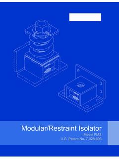
1 Installation of IsoMax Sound Isolation Clips Wall or CeilingStep 1 Attach clips per Kinetics layout guidelines for walls or ceilings. See attached layout 2 Secure clips with a single fastener on one end Use #8 x 2-1/2" coarse thread screwsSteel- Use #8, 10, or 12 x 1-5/8" self-tapping Type S screwsConcrete or Masonry- Use 3/16" dia x 2-1/4" Tapcon or equal anchorStep 3 Grip unsecured rubber end, snap in channel. Secure with second Channel RequirementsMinimum 25 ga with hemmed - 7/8" deep channelOptional - 1-1/2" deep channel for additional furring furring channel with a 6-in overlap and secure overlappedpieces with wire or screws per standard industry method for step 2.
2 Snap clipsonto furring channel. Hand slide clips toproper location on the furring both ends of the clip to secure Channel DimensionsLoad Specification forIsoMax ClipsThe IsoMax clip is designed to carry a drywall furring channel (hat track) with one or more layers of gypsum wall-board attached. THE LOAD CAPACITY OF THE CLIP DEPENDS ON THE GAGE OF FURRING CHANNEL , 25 ga, furring channel carries less load than 22 ga channel. The maximum design load capacity for theIsoMax clip in shear (wall application) or in tension (ceiling application) is as follows. Design load calculations arebased on tested loading to failure where the furring channel deforms and pulls Load Maximum forWall or Ceiling Application2:1 safety :1 safety factor*IsoMax clip with 25 ga steel furring channel45 clip with 22 ga steel furring channel60 : 5/8" thick gypsum wallboard weighs lbs/sq ft.
3 1/2" thick gypsum wallboard weighs lbs/sq ft.* Suggested safety factor of :1 for more critical life safety applications; , hospitalsInstallation of IsoMax Sound Isolation Clips - Walls and CeilingsSpacing of clips on the furring channel shall be a maximum of 48 inches. Spacing between furring channels shall be a maximum of 24 inches. Use only the required size and gage of furring channel per the Furring Channel Requirements section and LoadSpecification section of this document. (Walls only) The first layer of gypsum wallboard shall align seams between sheets on the centerline of the horizontal furring channels.
4 (Walls only) The bottom row of clips with furring channel(s) should be a maximum 3 inches to the center of thechannel from the floor. The top row should be within 6 inches of the ceiling. (Walls only) The first row of gypsum wallboard sheets at the bottom of the wall shall be installed with the longdimension supported on a 1/4 inch thick continuous resilient isolation strip, Kinetics Model RWS. (Ceilings only) The IsoMax clips should be within 12 inches of the ceiling perimeter at the end of the furring chan-nel run. (Ceilings only) The first row of channel at the ceiling perimeter should be a maximum 6 from the wall.
5 Furring channels are installed perpendicular to the framing InformationAll potential sound leaks; gaps around outlets, window, or door frames; pipe penetrations and the like should besealed with a non-hardening acoustical sealant or resilient putty. Note: See Kinetics Model Sealtight Outlet wall and ceiling assemblies and the specific construction requirements are listed at:Go to Certification Directory - Type Kinetics Noise Controlin Search by to Listings will be displayed.