Transcription of Subthreshold Operation and gm/Id design - CppSim
1 PerrottAnalysis and design of Analog Integrated CircuitsLecture 16 Subthreshold Operation and gm/IdDesignMichael H. PerrottApril 1, 2012 Copyright 2012 by Michael H. PerrottAll rights PerrottA Closer Look at Transconductance Assuming device is in strong inversion and in saturation:2 IdVgsId_op VVTHVgs_opVds > VM1 IdVgsNMOS gsdgm = Vgs IdVgs_opID= nCox2WL(Vgs VTH)2(1 + Vds) gm= Id Vgs nCoxWL(Vgs VTH) s2 nCoxWLId gm Idq2 nCoxW/L Id 2Id(Vgs VTH) PerrottUnity Gain Frequency for Current Gain, ft Under fairly general conditions, we calculate: ftis a key parameter for characterizing the achievable gain bandwidth product with circuits that use the device3|Id/Iin| PerrottCurrent Density as a Key Parameter Current density is defined as the ratio Id/W.
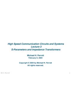
2 -We ll assume that current density is altered by keeping Idfixed such that only W varies Maintains constant power ro( , 1/gds= 1/( Id)) will remain somewhat PerrottInvestigating Impact of Current Density For simplicity, let us assume that the CMOS device follows the square law relationship-This will lead to the formulations:-These formulations are only accurate over a narrow region of strong inversion (with the device in saturation)-However, the general trends observed from the above expressions as a function of current density will provide useful insight5ID nCox2WL(Vgs VTH)2gm 2 IdVgs VTHVgs VTH s2L nCox IdW Perrott10 710 610 510 410 10 6 Gate Overdrive versus Current DensityVgs Vth (Volts)10 710 610 510 410 302468x 10 3 Transconductance versus Current Densitygm (1/Ohms)10 710 610 510 410 301234x 1011ft versus Current Densityft (Hz)Current Density Id/W (Amps/micron)
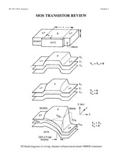
3 6 Investigate the Impact of Increasing Current DensitygmdecreasesftincreasesGate overdrive increasesgm 2 IdVgs VTHft=12 gmCgs WWVgs VTH s2L nCox IdW W decreased with fixed PerrottHigher gm(more gain)10 710 610 510 410 10 6 Gate Overdrive versus Current DensityVgs Vth (Volts)10 710 610 510 410 302468x 10 3 Transconductance versus Current Densitygm (1/Ohms)10 710 610 510 410 301234x 1011ft versus Current Densityft (Hz)Current Density Id/W (Amps/micron)7 Transconductance Efficiency Versus ftgmdecreasesftincreasesGate overdrive increasesgm 2 IdVgs VTHft=12 gmCgs WWVgs VTH s2L nCox IdW Higher ft(faster speed) PerrottWeak10 710 610 510 410 10 6 Gate Overdrive versus Current DensityVgs Vth (Volts)10 710 610 510 410 302468x 10 3 Transconductance versus Current Densitygm (1/Ohms)10 710 610 510 410 301234x 1011ft versus Current Densityft (Hz)Current Density Id/W (Amps/micron)8 Transistor Inversion Operating RegionsgmdecreasesftincreasesGate overdrive increasesgm 2 IdVgs VTHft=12 gmCgs WWVgs VTH s2L nCox IdW PerrottKey Insights Related to Current Density Current density sets the device operating mode-Weak inversion ( Subthreshold ): highest gmefficiency Achieves highest gmfor a given amount of current, Id-Strong inversion.
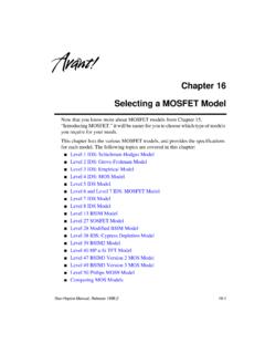
4 Highest ft Achieves highest speed for a given amount of current, Id-Moderate inversion: compromise between the two Often the best choice for circuits that do not demand the highest speed but cannot afford the low speed of weak inversion ( Subthreshold Operation ) Key issue: validity of square law current assumption-The above is only accurate over a narrow range of strong inversion ( , the previous plots are inaccurate) General observations above are still true, though9ID= nCox2WL(Vgs VTH)2(1 + Vds) PerrottA Proper Model for Subthreshold Operation Drain current:-Where:-Note: channel length modulation, , , is ignored here10ID=ID0 WLeVgs/(nVt) 1 e Vds/Vt n=Cox+CdeplCox <VTHVDSIDVt=kTq 26mV atT=300 KID0= nCox(n 1)V2te VTH/(nVt) PerrottSaturation Region for Subthreshold Operation Saturation occurs at roughly Vds> 100 mV11 ID=ID0 WLeVgs/(nVt) 1 e Vds/Vt ID0 WLeVgs/(nVt) current Versus Vds and VgsId (nA)Vds (Volts)Vgs = = = PerrottTransconductance in Subthreshold Region Assuming device is in Subthreshold and in saturation:12 IdVgsId_opVds > 100mVM1 IdVgsNMOS gsdgm = Vgs IdVgs_opVgs_op gm= Id Vgs ID0 WLeVgs/(nVt)1nVt=IdnVtRecall for strong inversion :gm 2Id(Vgs VTH)ID ID0 WLeVgs/(nVt)gmpurely afunction of Id!
5 PerrottComparison of Strong and Weak Inversion for gm Assumption: Idis constant with only W varying Strong inversion formulation predicts ever increasing gmwith reduced overdrive voltage-Reduced current density leads to reduced overdrive voltage and therefore higher gm Weak inversion formulation predicts that gmwill hit a maximum value as current density is reduced-Note that the area of the device no longer influences gmwhen operating in weak inversion ( , Subthreshold )13gm= IdnVtgm 2Id(Vgs VTH) PerrottvgsgmvgsCgsrogmbvsdgsdgsHybrid- Model in Subthreshold Region (In Saturation) Looks the same in form as for strong inversion, but different expressions for the various parameters-We can use the very same Thevenin modeling approach as in strong inversion We just need to calculate gmand gmbdifferentlygm 1n IdVtgmb n 1n IdVtro 1 PerrottvgsgmvgsCgsind2rogmbvsdgsdgsNoise for Subthreshold Operation (In Saturation)i2nd=4kT gdso f+Kffg2mWLC2ox f Recall transistor drain noise in strong inversion: In weak inversion ( , Subthreshold ).
6 Thermal noise1/f noisei2nd=2kT ngm f+Kffg2mWLC2ox fThermal noise1/f PerrottStrong Inversion Versus Weak Inversion Strong inversion (Vgs> VTH)-Poor gmefficiency ( , gm/Idis low) but fast speed-Need Vds> (Vgs VTH) = V to be in saturation-Key device parameters are calculated as: Weak inversion (Vgs< VTH)-Good gmefficiency ( , gm/Idis high) but slow speed-Need Vds> 100mV to be in saturation-Key device parameters are calculated as: Moderate inversion: compromise between the two16gm 2Id(Vgs VTH)gmb gm2q2| F|+VSBro 1 Idgm 1n IdVtgmb n 1n IdVtro 1 IdThevenin Modeling Techniques Can Be Applied to All Perrottgm/IdDesign gm/Iddesign is completely SPICE based-Hand calculations of gm, ro, etc.
7 Are not performed Various transistor parameters are plotted in terms of gm/Id -Low gm/Idcorresponds to strong inversion-High gm/Idcorresponds to weak inversion Once a given value of gm/Idis chosen, it constrains the relationship between W, L, ft, etc. such that the sizing of devices becomes a straightforward PerrottUseful References Related to gm/IdDesign Prof. Bernhard Boser s Lecture:-B. E. Boser, "Analog Circuit design with Submicron Transistors," IEEE SSCS Meeting, Santa Clara Valley, May 19, 2005, Prof. Boris Murmann s Course Notes: - See Slides 45 to 67 in particular Prof. Reid Harrison s paper on a low noise instrument amplifier:- ~ Perrott19 Summary CMOS devices in saturation can be utilized in weak, moderate, or strong inversion-Each region of Operation involves different expressions for drain current as a function of Vgsand Vds-It is best to use SPICE to calculate parameters such as gm, gmb, rodue to the complexity of the device model in encompassing these three operating regions gm/Idmethodology is one such approach-Weak inversion offers large gm/Idbut slow speed.
8 And strong inversion offers fast speed but lower gm/Id -Moderate inversion offers the best compromise between achieving reasonable gm/Idand reasonable speed Thevenin modeling approach is valid for all operating regions once gm, gmb, and roare know