Transcription of Switch Amplifier KFD2-SR2-Ex2.W Features Assembly
1 Release date 2018-06-19 07:42 Date of issue to "General Notes Relating to Pepperl+Fuchs Product Information".Pepperl+Fuchs GroupUSA: +1 330 486 0002 Singapore: +65 6779 9091 Germany: +49 621 776 Amplifier2+3-1+Zone 2 Div. 2 Zone 0, 1, 2 Div. 1, V DC14+15-Power Rail24 V DCERR5+6-4+10 k 10 k 400 R 2 k 10 k 10 k 400 R 2 k ConnectionAssembly 2-channel isolated barrier 24 V DC supply (Power Rail) Dry contact or NAMUR inputs Relay contact output Line fault detection (LFD) Reversible mode of operation Up to SIL 2 acc. to IEC 61508 FunctionThis isolated barrier is used for intrinsic safety applications. It transfers digital signals (NAMUR sensors/mechanical contacts) from a hazardous area to a safe proximity sensor or Switch controls a form C changeover relay contact for the safe area load.
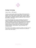
2 The normal output state can be reversed using switchesS1 and S2. Switch S3 is used to enable or disable line fault detection of the field an error condition, the relays revert to their de-energized state and the LEDs indicate the fault according to NAMUR unique collective error messaging feature is available when used with the Power Rail CHK PWRS2S1S3 IIIF ront viewLED yellow:Relay output LED red:LB/SC channel LED yellow:Relay output LED red:LB/SC channel Switch S3(LB/SC-monitoring) LED green:Power supplyRemovable terminalsgreen Removable terminalsblue Switch S1(Mode of operation channel ) Switch S2(Mode of operation channel ) Release date 2018-06-19 07:42 Date of issue to "General Notes Relating to Pepperl+Fuchs Product Information".
3 Pepperl+Fuchs GroupUSA: +1 330 486 0002 Singapore: +65 6779 9091 Germany: +49 621 776 specificationsSignal type Digital InputFunctional safety related parametersSafety Integrity Level (SIL) SIL 2 SupplyConnection Power Rail or terminals 14+, 15-Rated voltage Ur20 .. 30 V DCRipple 10 %Rated current Ir 50 mAPower dissipation 1 WPower consumption < WInputConnection side field sideConnection terminals 1+, 2+, 3-; 4+, 5+, 6-Rated values acc. to EN 60947-5-6 (NAMUR)Open circuit voltage/short-circuit current approx. 8 V DC / approx. 8 mASwitching point/switching hysteresis .. mA / approx. mALine fault detection breakage I mA , short-circuit I > 6 mAPulse/Pause ratio 20 ms / 20 msOutputConnection side control sideConnection output I: terminals 7, 8, 9 ; output II: terminals 10, 11, 12 Output I, II signal, relayContact loading 253 V AC/2 A/cos > ; V AC/4 A/cos > ; 40 V DC/2 A resistive loadMinimum Switch current 2 mA / 24 V DCEnergized/De-energized delay approx.
4 20 ms / approx. 20 msMechanical life 107 switching cyclesTransfer characteristicsSwitching frequency 10 HzGalvanic isolationInput/Output reinforced insulation according to IEC/EN 61010-1, rated insulation voltage 300 Veff Input/power supply reinforced insulation according to IEC/EN 61010-1, rated insulation voltage 300 Veff Output/power supply reinforced insulation according to IEC/EN 61010-1, rated insulation voltage 300 Veff Output/Output reinforced insulation according to IEC/EN 61010-1, rated insulation voltage 300 Veff Indicators/settingsDisplay elements LEDsControl elements DIP-switchConfiguration via DIP switchesLabeling space for labeling at the frontDirective conformityElectromagnetic compatibility Directive 2014/30/EU EN 61326-1:2013 (industrial locations)Low voltage Directive 2014/35/EU EN 61010-1:2010 ConformityElectromagnetic compatibility NE 21:2006 Degree of protection IEC 60529:2001 Input EN 60947-5-6.
5 2000 Ambient conditionsAmbient temperature -20 .. 60 C (-4 .. 140 F)Mechanical specificationsDegree of protection IP20 Connection screw terminalsMass approx. 150 gDimensions 20 x 119 x 115 mm ( x x inch) , housing type B2 Mounting on 35 mm DIN mounting rail acc. to EN 60715:2001 Data for application in connection with hazardous areasEU-Type Examination Certificate PTB 00 ATEX 2080 Marking II (1)G [Ex ia Ga] IIC II (1)D [Ex ia Da] IIIC I (M1) [Ex ia Ma] IInput Ex iaVoltage VCurrent Io13 mARelease date 2018-06-19 07:42 Date of issue to "General Notes Relating to Pepperl+Fuchs Product Information".
6 Pepperl+Fuchs GroupUSA: +1 330 486 0002 Singapore: +65 6779 9091 Germany: +49 621 776 Po34 mW (linear characteristic)Supply Maximum safe voltage Um253 V AC / 125 V DC (Attention! Um is no rated voltage.)Output Contact loading 253 V AC/2 A/cos > ; V AC/4 A/cos > ; 40 V DC/2 A resistive load Maximum safe voltage Um253 V AC (Attention! The rated voltage can be lower.)Fault indication output Maximum safe voltage Um40 V DC (Attention! Um is no rated voltage.)
7 Certificate PF 08 CERT 0803 Marking II (3)G [Ex ic Gc] IICI nput Ex icVoltage VCurrent Io13 mAPower Po34 mW (linear characteristic)Output Contact loading 253 V AC/2 A/cos > ; V AC/4 A/cos > ; 40 V DC/2 A resistive loadCertificate T V 99 ATEX 1493 XMarking II 3G Ex nA nC IIC T4 Output Contact loading 50 V AC/4 A/cos > ; 40 V DC/2 A resistive loadGalvanic isolation Input/Output safe electrical isolation acc. to IEC/EN 60079-11, voltage peak value 375 VInput/power supply safe electrical isolation acc. to IEC/EN 60079-11, voltage peak value 375 VDirective conformity Directive 2014/34/EU EN 60079-0:2012+A11:2013 , EN 60079-11:2012 , EN 60079-15:2010 International approvalsFM approval Control drawing 116-0035UL approval Control drawing 116-0145 CSA approval Control drawing 116-0047 IECEx approval IECEx PTB for [Ex ia Ga] IIC, [Ex ia Da] IIIC, [Ex ia Ma] IGeneral informationSupplementary information Observe the certificates, declarations of conformity, instruction manuals, and manuals where applicable.
8 For information see date 2018-06-19 07:42 Date of issue to "General Notes Relating to Pepperl+Fuchs Product Information".Pepperl+Fuchs GroupUSA: +1 330 486 0002 Singapore: +65 6779 9091 Germany: +49 621 776 feed module kfd2 -EB2 The power feed module is used to supply the devices with 24 V DC via the Power Rail. The fuse-protected power feed module can supply up to 150 individual devices depending on the power consumption of the devices. Collective error messages received from the Power Rail activate a galvanically-isolated mechanical Rail UPR-03 The Power Rail UPR-03 is a complete unit consisting of the electrical insert and an aluminium profile rail 35 mm x 15 mm. To make electrical contact, the devices are simply Rail K-DUCT with Power RailThe profile rail K-DUCT is an aluminum profile rail with Power Rail insert and two integral cable ducts for system and field cables.
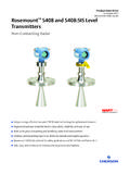
9 Due to this Assembly no additional cable guides are Rail and Profile Rail must not be fed via the device terminals of the individual devices!Configuration7891011121234561314 1512 PWRCHKOUTS1S2S3123123S1S3 IIS2 ISwitch positionOperating statusFactory settings: Switch 1, 2 and 3 in position ISFunctionPosition1 Mode of operationOutput I (relay)energizedwith high input currentIwith low input currentII2 Mode of operationOutput II (relay)energizedwith high input currentIwith low input currentII3 Line fault detectionONIOFFIIC ontrol circuitInput signalInitiator high impedance/contact openedlow input currentInitiator low impedance/contact closedhigh input currentLead breakage,lead short-circuitLine faultAccessories