Transcription of Switching Loss Estimation of SiC MOSFET in LTspice
1 International Journal of Advance Electrical and Electronics Engineering (IJAEEE) _____ _____ ISSN (Print): 2278-8948, Volume-4 Issue-4, 2015 5 Switching loss Estimation of SiC MOSFET in LTspice 1 Mary Suja Antony, Praveen Raj 1,2 EEE Dept., MBCET, Trivandrum, Kerala, India Abstract Silicon carbide (SiC) is the most promising material for future demands, especially in high voltage, high temperature, high efficiency and high power density operations. This paper consists of Switching characteristic study of 1200V, 35A SiC MOSFET using double pulse test circuit in LTspice simulation platform.
2 SiC spice model given by the manufacturer is used in the LTspice software tool to estimate the turn on and turn off loss of the device. The test is carried out at 32 C and 125 C ambient condition and the results are compared. Keywords SiC MOSFET , Double pulse test, LTspice , Switching loss , characteristics, Turn on loss , Turn off loss , temperature effects, band gap I. INTRODUCTION Presently, Si insulated-gate bipolar transistors (IGBTs) are able to handle high voltage, over 5 KV and high current over 1000 A, whereas the bipolar nature of the device limits the Switching frequency of converter systems below 100 kHz and thus the efficiency of the system.
3 On the other hand, Si Metal-Oxide- Semiconductor Field Effect Transistors ( mosfets ), although ideal for high- Switching -frequency applications up to the MHz, suffer from relatively high on-state resistance and hence high conduction loss as the blocking voltage increases, which virtually constrains the use of the device in medium and low voltage applications less than 600 V. The general 150 C limit of the maximum junction temperature further blocks the use of Si devices in high-power-density and high-temperature situations.
4 All these disadvantages of Si based semiconductor devices is because of its narrow band gap. Si has a band gap value of Silicon has narrow band gap, so when the temperature rises, there is an exponential increase in intrinsic carriers. This causes the value of undesired leakage currents high and at even higher temperatures, the intrinsic carriers make uncontrolled conductivity and it will overcome the semiconductor device operation. The same reasoning can be extended to the breakdown voltage of a device.
5 Si devices have reached their maximum theoretical limits. Theoretically, wider band gap devices like SiC, GaN and Diamond has the potential to overcome the above mentioned issues. Silicon Carbide (SiC) is a compound semiconductor made of equal parts silicon and carbon in a perfect crystal lattice. The bonds between the carbon and silicon atoms in SiC are stronger than the bonds between silicon atoms in silicon. The wide energy band gap ( eV) of SiC is one of its main advantages. It leads to a higher critical field for breakdown and a higher threshold for creation of soft errors from ionizing radiation since higher energy is needed to thermally create electron-hole pairs.
6 Due to the high electric breakdown field, SiC -based power devices have high breakdown voltages. As a result, SiC-based devices have several advantages over Si-based devices such as reduced energy losses and high Switching frequency which assist to increase the efficiency and reduce the converter weight and size. This is particularly important for aerospace and military applications which are highly sensitive to weight and size requirements. [1][2][3] MOSFET losses includes mainly Switching loss (Turn on and Turn off loss ), conduction loss and reverse recovery loss of diode.
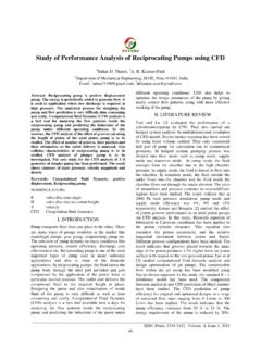
7 At turn-on time, the device current rises from the negligibly small leakage current to the on-state current while the device voltage falls from the off-state voltage to small on-state voltage. This contributes to turn on loss (Eon loss ). At turn-off the device current falls from the on-state current to small leakage current while the device voltage falls from the constant voltage to the high off-state voltage. This contributes to turn off loss (Eoff loss ). The turn-on and turn-off losses are proportional to the Switching frequency.
8 II. LTspice SIMULATION Turn on and Turn off loss is estimated for different voltages and current using Rohm make SCH2080KE (1200V, 35A) SiC MOSFET . Spice model given by the manufacturer is used in the LTspice IV software tool to estimate the Switching loss . The spice model statement is included in the spice directive list in LTspice . Double pulse test is used to analyze the Switching characteristics of a device. Variable DC supply is used to estimate the Switching losses of the device at different voltages.
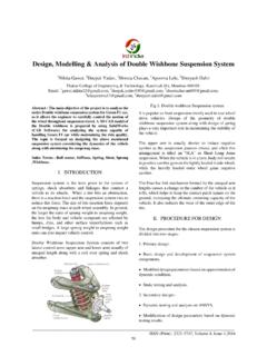
9 The upper device acts as a freewheeling diode (gate and source terminals are shorted) for the inductive load of 860 H. International Journal of Advance Electrical and Electronics Engineering (IJAEEE) _____ _____ ISSN (Print): 2278-8948, Volume-4 Issue-4, 2015 6 Double Pulse Test circuit in LTspice The first turn on pulse establishes the desired current value by building up the inductor current. The gate pulse width of the Switching device (M1) is adjusted to achieve the desired current value (t = LI/V) for a particular voltage.
10 During the turn off pulse the inductor current freewheels through the diode (M2). The energy loss in this interval corresponds to the turn off loss of the device. In the second turn on pulse the desired current flows through the Switching device (M1) for a very short duration of time. The energy loss at this interval corresponds to the turn on loss . Vds * Id integrated over time gives the energy loss of the device. The test is carried out with 5 Gate resistance at 32 C and 125 C ambient condition.