Transcription of Technical Guide: Introduction to Liquid Pipeline …
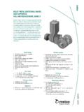
1 Technical GuideFebruary 2012An Introduction to Liquid Pipeline Surge Relief Technical GuideTypical tank and pressure vessel systems are required to release pressure without passing large volumes of Liquid . Usually these systems operate to relieve vapor from the space above the Liquid using self acting pressure relief valves . An example of such a valve is shown Acting Pressure Relief Valve Although these valves are commonly used as pressure relief devices, the nozzle size is quite small and hence the capacity for passing liquids is extremely limited. Therefore, such designs are limited to tank and vessel protection, where overpressure is readily relieved without the need to pass significant quantities of many applications, such as pipelines, storage terminals and marine loading and unloading, it is necessary to include surge relief systems for the purpose of equipment and personnel protection.
2 Surge pressures result from a sudden change in fluid velocity and, without surge relief, these surge pressures can damage pipes, other piping components, equipment and pressure surges can be generated by anything that causes the Liquid velocity in a line to change quickly ( , valve closure, pump trip, Emergency Shut Down (ESD) closure occurs) and subsequently packing pressure. Total surge pressure may be significantly above the maximum allowable pressure of the system, leading to serious damage to your valuable assets. The fundamental requirements of surge relief systems include the need for fast acting, high capacity valves which can open very quickly to remove surge pressures from the line and then return to the normal (closed) state quickly but without causing additional pressure surge during closure.
3 These valves are often required to open fully in very short periods of time, so that they may pass the entire flowing stream if conditions pipelines can produce dangerous pressures when static product is shut-in between valves and thermal expansion occurs. In this situation, pressure relief will be required. Although the time of operation and valve capacities are not as crucial in such applications, they remain as key elements of safety in the system and proper regard to selection and operation is general, all systems where pressure is contained must have some form of pressure relief, which is often mandated and regulated by local authorities.
4 The design of such systems is dependent on a complex range of factors including, but not limited to, the potential for pressure increases, the volumes which must be passed by the pressure relief equipment in operation and the capacity of the system to contain Importance of Surge February 2012An Introduction to Liquid Pipeline Surge Relief In bulk Liquid transportation, safety systems in the form of pressure control, pressure regulation and surge relief valves are required. In the United States, Department of Transportation (DOT) mandate guidelines. DOT Title 49 CFR Part states: No operator may permit the pressure in a Pipeline during surges or other variations from normal operations to exceed 110% of the operating pressure limit established under paragraph (a) of this section.
5 Each operator must provide adequate controls and protective equipment to control pressure within this limit .840 720 600 480 360 240 120 10 0 0 20 30 40 50 Time In SecondsPressure psigSurge Pressure would be abated if larger surge relief valve was used Without surge relief controlWith surge relief controlSetpointNote: Figure adapted from Sliding-plug Surge Relief Valve Helps Meet DOT Requirements , Pipeline Industry, January potential for damage may be illustrated by the following graph showing the effects of the closure of an ESD valve. Without surge relief the pressure spikes to around 10 times the normal line pressure. As the pressure wave created propagates along the line, the cycling effect occurs.
6 The effect on pressure if a surge pressure relief valve is used (shown below). The larger the capacity of the surge relief control valve, the lower the pressure spike. Typical Applications for Surge Control Technical Guide761 Pressure Relief ValveTypical Application for the 761 Pressure Relief Valve (pump pressure relief)Model 761 ValvePUMPD aniel Pilot Operated Pressure Relief valves The Daniel 761 Valve is a pilot operated pressure relief valve used for pump protection duty and for similar applications where pressure relief is required to maintain pressure at a given set is controlled to within 2 psi regardless of upstream conditions.
7 The pilot and main valve are single seated valves with high capacities. These valves protect the line against excessive pressure and surge or as a pump bypass to maintain a constant pump discharge of Surge Control valves February 2012An Introduction to Liquid Pipeline Surge Relief Nitrogen Loaded Surge Relief valves For applications where exceptionally fast response times are required, customers need to use gas loaded systems. Pipeline surge relief applications call for the minimum possible operating times and valves which can open fully when required. These valves are normally closed and open on increasing inlet pressure. The basic valve is the balanced piston design.
8 Nitrogen gas is used to pressurize the valve piston to keep it in the closed position. The valve incorporates an integral oil reservoir mounted on the external surface of the cylinder head, which upon installation is partially filled with a light oil. Gas under pressure is applied to the reservoir. The pressure of the nitrogen gas, minus the 4 psi (force of the valve spring) is the effective set point of the valve. When the Pipeline pressure is less than this total force, the valve will be tightly closed. As Pipeline pressure increases the spring and gas pressure is overcome and the valve opens. The oil is a moveable barrier between the gas and valve piston.
9 This should eliminate any possibility of gas permeating the piston seal which would result in gas bypassing the piston and gas valve may be mounted in a 45 angle position, horizontally or vertically. Whichever orientation is specified, the oil reservoir must be valves are capable of handling dirty and viscous products and are extremely easy to size, operate and maintain. The entire internal assembly is removable as a cartridge without the need to remove the body from the line. This is designed without any internal parts to obstruct the relief path. This further minimizes debris accumulation, which could inhibit valve operation in emergency relief Daniel Nitrogen Loaded Surge Relief Valve operates on a hydraulically balanced-piston principle.
10 When pressures on both sides of the piston are equalized, a spring located on top of the piston acts as a differential force and closes the piston. When the pressure against the bottom of the piston exceeds the pressure plus the force of the spring exerted against the top of the piston, spring tension is overcome, and the valve opens. Opening and closing speed is controlled by a check valve mounted to the internal surface of the cylinder head and is relatively unrestricted. The result is fast-opening response. Closing speed is controlled by a fixed orifice in the check valve. Daniel Surge Relief Valve for 45 installationDaniel Surge Relief Valve for vertical installationDaniel Surge Relief Valve for horizontal Technical GuideSurge Relief Valve Closed PositionLine pressure on the nose of the piston is equally transmitted to the spring side of the piston.


