Transcription of Temperature Control Thermometers Temperature Control …
1 SERVICE MANUAL - ALL MODELSTEMPERATURE CONTROLS/ SERVICE MANUAL fi ALL MODELST emperature Control RepairsTEMPERATURE CONTROLS/THERMOMETER/TIMERSTRUETECHNICAL SERVICE MANUAL - ALL 1 - Control must operate within its pre-calibrated range of 2 - Cut-in is the ON 3 - Cut-out is the OFF : All temps are at mid-point setting #5. All temps advised have a +/- 2 degree TO DIAGNOSEC onfirmed CalibrationTRUE P/NMFG P/NAPPLICATIONCUT-INCUT OUT8003039531N37635158003049530N1490-9-1 58003069531N25140198003129530N1284-8-158 003139531N33537168003209530N118533278003 259530N1318 RED WINE, CHOCOLATE62558003359530N1376382080034095 30N11552611800345077B1264-3-168003579530 266-3-8800358077B1214-9-148003639530C311 -3-13800366077B68063717800368077B6857422 3800369077B1212-3-12800370077B1216-14-25 800371077B68634224800382077B685637188003 83077B12270-6800384077B12292519800385077 B1228 WHITE WINE4334800386077B68714120800387077B6887 FLOWER COOLER39218003909530N1329 SUPER NOVA138800393077B68274221800395931N370 HIGH ALTITUDE40238003999530C3040-5822212 CAP-075-174 RHEATED822213077B68943722822214077B13093 117822223077B1331269831931077B1277-2-983 19323 ART56 VAA44018831987077B0995 RED WINE.
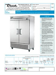
2 CHOCOLATE5750908854077B69263610908975077 B1352-16-32911427077B13543826913382077B1 367-11-23917838077B13690-14930794091X977 54225933190091X979642199587453 ART55 VAA43918958747095X0028379588573 ART5 VAA1988-69592683 ART55 VAA340269606403 ART55 VAA543209627283 ART55 VAA642209630563 ART55 VAA23916 All temps are at mid-point setting #5 All temps advised have a +/- 2 degree varianceSUBJECT TO CHANGETRUETECHNICAL SERVICE MANUAL - ALL TO CHECK THE CUT-IN AND CUT-OUT OPERATION OF A Temperature CONTROLSTEP 1 - Disconnect the power to the 2 - Locate the Temperature Control and note its setting. The Temperature Control should be set at mid-range, about : If the Control was set to high (colder) this could be why the product is freezing. Reset the Control and check the cabinet operation in 24-48 hours. You may have to use your multi-meter to check and see if the Control has power and is 3 - Remove the four 1/4" hex head screws that secure the fan guard in place.
3 This will expose the evaporator motor fan blade. Keep in mind that there might be more than one evaporator fan 4 - Remove the nut that holds the fan blade in place. See image 5 - Remove the fan blade. If there are additional fan blades remove all. See image 3 STEP 6 - Insert your digital thermometer into the evaporator coil as close to the tem-perature Control copper tube as possible. This would be to the right side of the opening. See image 7 - Plug the unit in. The compressor should come on. The evaporator Temperature will come down very fast allowing you to see approximately what Temperature the Control opened up and the compressor shut off. This is your cut-out point. Check this against the spec s for the Control to determine if the operation is where is should be. NOTE: This process should not take more than 10 minutes. If it does, there might be a problem with the refrigeration 8 - Open up the cabinet door (s) to allow the warm air to come into the cabinet.
4 This will warm up your evaporator coil and close the Temperature Control , turning the compressor on. This is your cut-in point. Check this against the spec s for the Control to determine if the operation is where it should be. THE TEMPERATURES THAT YOU READ COULD BE + 2 9 - Based on your findings you may have to replace or adjust the Control Repeat Steps 7 and 8 several times to verify the operation after you have made the necessary 10 - Remove the power cord. Starting with Step 5 and working backwards place the fan blade and fan guard in place and put the unit back 11 - Plug the unit back of the cooler Temperature controls are coil sensing constant cut-in INSTRUCTIONS Tools Required 1/4" Nut Driver of Socket Digital Thermometer of Equivalent Multi-Meter (Optional)1234 TRUETECHNICAL SERVICE MANUAL - ALL Temperature CONTROLS IN GDM-7, GDM-10, AND GDM-12 MODELS (OLD MODELS)STEP 1 - Unplug Cooler and turn Temperature Control to off ( 0 )
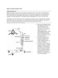
5 2 - Pull off the black Control knob from the 3 - Remove the mounting plate from the evaporator 4 - Remove the Temperature Control from the plate and dis-connect the 2 5 - Remove the lamp from the front of the cooler and re-move the front 6 - Reach in to the side of the evaporator coil and remove the permagum from around the Control bulb. Then remove the old thermostat Control bulb from the sleeve 7 - Insert the new thermostat Control bulb into the new copper sleeve extension until about 1/2 inch protrudes from the swaged end. Using a low Temperature lubricant on the Control bulb is 8 - Using the protruding end of the Control bulb as a guide, insert it into the copper sleeve (elbow) in the rear of the evaporator. Then push the sleeve extension over the end of the elbow to lock the two tubes 9 - Gently push the Control bulb through the joined sleeves in 1-2 inch increments until it reaches the end inside the evaporator, taking care not to kink the line.
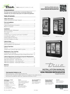
6 STEP 10 - Seal both ends of the new Control sleeve with permagum to keep moisture 11 - Remove the mounting plate from the evaporator housing. Connect the 2 wires to the new Control , the Control to the mounting plate, the plate to the cooler, and replace the Control knob . STEP 12 - Turn the Control knob to the #5 13 - Reassemble front of cooler and plug it INSTRUCTIONS New Copper Sleeve ExtensionPermagumTemperatureControlStand ardCopperSleeveEVAPORATORFRONT OF COOLERTRUETECHNICAL SERVICE MANUAL - ALL 1 - Removing Power : Disconnect power to the 2 Slide DoorRemove Louvered Grill:A. To remove grill, loosen upper screw on each end of grill and remove lower screws. Gently swing grill forward and DoorRemove Louvered Grill:A. Remove screws as indicated by 3 - Accessing Wire Connections:A. Remove ballast box cover by back-ing out two hex head screws.
7 (See Image 2).NOTE: Wiring diagram is positioned on inside 4 - Relay Connection Mounting:A. With slotted screw driver and plastic mallet or hammer, drive out knock out positioned on left side of ballast box. (See Image 3).B . Install the supplied grommet* into the knockout hole. (See Image 4).C . Mount relay to underside of unit on the left side of ballast box, and 3/4" back from the front edge of the : Mount relay next to the bal-last box, so that when the relay shield is installed it covers the relay and all exposed wiring. INSTALLATION INSTRUCTIONS WARNING: Failure to disconnect power to the unit may result in electrocution to field Repair Personnel These repairs should be performed by a qualified service Required Phillips-head Bit 1/4" Nut Driver Bit Wire Cutters Drill Needle-Nose Pliers Wire Strippers Crimping Tool Voltmeter Plastic Mallet or Hammer Slotted Screwdriver Contents of Relay Kit Relay (and mounting screws) Relay Shield (and mounting screws) (4) Relay wires: 2 blacks, 1 pink, 1 white with insulated female spade connectors on one end.
8 Grommet (4) Sta-con connectors New Temperature Control Instructions1a - Removing louvered grill (slide door model)1b - Removing louvered grill (swing door model)2 - Removing ballast box cover3 - Driving out knockout4 - Installing the grommetTEMPERATURE Control REPLACEMENT (FOR GDM & T-SERIES FREEZER CABINETS WITH LARGER THAN 1/3 COMPRESSORS) WITH DANFOSS SERVICE MANUAL - ALL should be anchored with two self-tapping screws, (supplied in kit), as pictured in Image 5. STEP 5 - Relay Temperature Control Wiring:A. Connect the wires included in kit to the relay as follows: 1. Connect one black wire to one of the normally open contacts of the Connect the other black wire to the other normally open contact on the Connect the pink wire to one side of the relay Connect the white wire to the other side of the relay coil.
9 NOTE: Each relay has a wiring diagram on the side of it. (See Illustration 6).B . Feed wires into the ballast box through the knockout. (See Image 7).C . Using the Sta-Con connectors in the relay kit, make the following connections inside the ballast box:1. Locate the pink wire coming from the Temperature Control and connecting to the black compressor receptacle wire. Cut this connection and connect this pink wire from the temp Control to the pink wire going to the relay. 2. Connect one black wire on relay to the black wire cut from the compressor Connect the white wire coming from the relay to the white wire bundle that is connected to the white on the main power cord. 4. Connect one black wire to the black wire bundle that is connected to the outgo-ing terminal on the main power switch located on the ballast 6 - Replace existing Temperature Control with new Danfoss Control in repair kit: (See Image 8).
10 A. Connect one pink wire from old Control to terminal #4 on new Temperature . Connect other pink wire from old Control to terminal #3 on new Danfoss tempera-ture - Anchoring relay7 - Routing relay wires8 - Temperature Control leads6 - Relay wiring diagramTRUETECHNICAL SERVICE MANUAL - ALL 7 - Anchor the Relay Shield: (See Image 9).A. Secure the new relay by attaching the relay shield. B . Relay shield includes two self-tapping screws. When installing shield, place shield in position to cover relay and all exposed 8 - Checking Relay Operation:A. Unplug the condensing unit from the compressor receptacle ( located on the ballast box).B . Turn the new Control to the 0 , (zero), position by aligning the zero indication on Control knob with the arrow stamped into the evaporator housing. Ensure that con-trol is off by listening for an audible click.