Transcription of The Effect of Coating and Potting on the Reliability of ...
1 The Effect of Coating and Potting on the Reliability of QFN devices By: Greg Caswell and Cheryl Tulkoff DfR Solutions 443-834-9284, 512-328-5687 Abstract The fastest growing package types in the electronics industry today are Bottom Termination Components (BTCs). While the advantages of BTCs are well documented, they pose significant Reliability challenges to users. One of the most common drivers for Reliability failures is the inappropriate adoption of new technologies. This is especially true for new component packaging like BTCs.
2 Obtaining relevant information can be difficult since information is often segmented and the focus is on design opportunities not on Reliability risks. Most users have little influence over component packaging and most devices offer only one or two packaging styles. And, when faced with challenges, users typically fall back on tried and true solutions that may not work for new packaging. This has already occurred with BTC components. Commonly used conformal Coating and Potting processes have resulted in shortened fatigue life under thermal cycling conditions.
3 Why do conformal Coating and Potting reduce fatigue life? This paper details work undertaken to understand the mechanisms underlying this reduction. Verification and determination of mechanical properties of some common materials are performed and highlighted. Recommendations for material selection and housing design are also given. Basically, the lack of a compliant lead structure makes BTC devices more susceptible to PCB warpage related failures so proper precautions must be taken to ensure adequate fatigue life for high Reliability applications.
4 Introduction Since the advent of Surface Mount Technology (SMT) in the mid 1970 s the electronics industry has continued to evolve from a packaging perspective by continually reducing the size of the component packages. First there were leadless chip carriers, later Ball Grid Arrays, Chip Scale Packages, and more recently Bottom Terminated Components. These package types are primarily designed for low cost applications or for products where a short lifetime is acceptable ( cell phones). However, designers have been incorporating BTCs into products that expected to survive environmental stresses for prolonged periods of time.
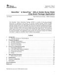
5 This paper will address the effects that conformal Coating and Potting have on these BTC packages and offer a new technology that may provide additional Reliability benefit. What is a QFN? A QFN (Quad Flat Pack No Lead) or Quad Flat Non-Leaded has been called the poor man s ball grid array (BGA). It has also been identified as a Leadframe Chip Scale Package (LF-CSP), MicroLeadFrame (MLF), MLP = molded lead package, LPCC Leadless Plastic Chip Carrier, QLP = Quad Leadless Package, HVQFN = heatsink very thin QFN. This package type utilizes an overmolded leadframe with bond pads exposed on the bottom and arranged along the periphery of the package as shown in Figure 1.
6 Figure 1 Typical QFN Cross Section The package was developed in the early to mid-1990 s by Motorola, Toshiba, Amkor, etc. and was standardized by JEDEC/EIAJ in the late-1990 s. It is the fastest growing package type in the electronics industry today. Advantages There are several distinct advantages for the selection of BTC/QFN packaging for current applications. The elimination of leads provides lower resistance, lower inductance, higher performance and higher package densities. The packaging configuration has a more direct thermal path with larger area: Die Die Attach Thermal Pad Solder Board Bond Pad Also, the Ja for the QFN is about half that of a leaded counterpart (as per JESD-51) which in turn allows for a 2X increase in power dissipation capability.
7 The rate of heat transfer between two bodies may be quantified in terms of the thermal resistance between them. In the simple model mentioned above, the over-all thermal resistance between the die and the surroundings of the device, ja ('ja' stands for 'junction-to-ambient') is the sum of two thermal resistances: 1) the thermal resistance between the die and the package, jc ('jc' stands for 'junction-to-case'); and 2) the thermal resistance between the package and the surroundings, ca ('ca' stands for 'case-to-ambient'). Table 1 summarizes this comparison with other packaging formats.
8 Table 1 Theta Ja Comparison of QFN package to Other packaging Formats At higher operating frequencies, inductance of the gold wire and long lead-frame traces will affect performance of the circuit. Another advantage of the QFN package is that its inductance is half its leaded counterpart because it eliminates gullwing leads and shortens wire lengths. Disadvantages Conversely, the QFN package also inherently has increased power density, manufacturability issues and is more susceptible to thermal mechanical fatigue.
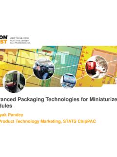
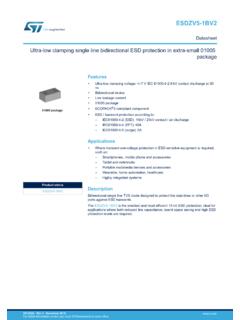
9 The transition from older packaging approaches ( Quad Flat Packs (QFP) to Ball Grid Array (BGA) to BTC/QFN has seen a declining level of ability to survive temperature cycling as illustrated in Figure 2. The cycles to failure identified are as a result of -40 to +125 C thermal cycles. QFP >10,000 Cycles BGA 3000 to 8000 cycles BTC/QFN 1000 to 3000 cycles Figure 2 Comparison of Thermal Cycles to Failure for QFP, BGA, and BTC/QFN packages On numerous equations, DfR has documented that the increased die to package ratio in QFN and CSP packages has resulted in a reduction in fatigue life.)
10 Figure 3 illustrates this concept. As the ratio increases, the fatigue life decreases, from a 40% ratio where the fatigue life is 8000 hours to a ratio of 70% where it is approximately 1000 hours. As DfR has shown, the Bottom Terminated Component (BTC-QFN) has significant positives and negatives with respect to using this type of package in high Reliability applications. Another area that is of concern is the use of conformal coatings or Potting compounds and their impacts on BTC packages. Figure 3 Ratio of Die to Package Size versus Fatigue Life.