Transcription of The FET Constant-Current Source/Limiter
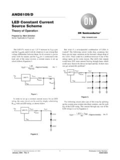
1 AN103 Siliconix10-Mar-97 1 The FET Constant-Current Source/LimiterIntroductionThe combination of low associated operating voltage andhigh output impedance makes the FET attractive as aconstant- current source. An adjustable- current source (Fig-ure 1) may be built with a FET, a variable resistor, and asmall battery. For optimum thermal stability, the FET shouldbe biased near the zero temperature coefficient +Figure Transistor current SourceRSRLNO TAGW henever the FET is operated in the current saturated re-gion, its output conductance is very low. This occurswhenever the drain-source voltage VDS is at least 50%greater than the cut-off voltage VGS(off). The FET may bebiased to operate as a Constant-Current source at any cur-rent below its saturation current Source BiasingFor a given device where IDSS and VGS(off) are known, theapproximate VGS required for a given ID is(1)VGS VGS(off) 1 IDIDSS 1 k where k can vary from to , depending on device ge-ometry.
2 If K = , the series resistor RS required betweensource and gate is(2)RS VGSIDorRS VGS(off)ID 1 IDIDSS A change in supply voltage or a change in load imped-ance, will change ID by only a small factor because of thelow output conductance goss. ID = ( VDS)(goss)(3)The value of goss is an important consideration in the ac-curacy of a Constant-Current source where the supply volt-age may vary. As goss may range from less than 1 S tomore than 50 S according to the FET type, the dynamicimpedance can be greater than 1 M to less than 20 k .This corresponds to a current stability range of 1 A to50 A per volt. The value of goss also depends on the op-erating point. Output conductance goss decrease approxi-mately linearly with ID.
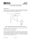
3 The relationship is(4)IDIDSS gossg osswhere goss = g oss(5)when VGS = 0(6)So as VGS VGS(off), goss Zero. For best regulation,ID must be considerably less than for Low gossIt is possible to achieve much lower goss per unit ID bycascading two FETs, as shown in Figure +SDFigure FET current SourceVDDRSRLQ2Q1 Updates to this app note may be obtained via facsimile by calling Siliconix FaxBack, 1-408-970-5600. Please request FaxBack document # 2 Siliconix10-Mar-97 DSDS + + +(a)(b)Figure FET VGS1 = 0Q2Q1 VGS2gfs2goss2I2 VDS2goss1 VDS1 = VGS2= IO/goss1 IOVONow, ID is regulated by Q1 and VDS1 = VGS2. The dc val-ue of ID is controlled by RS and Q1. However, Q1 and Q2both affect current stability.
4 The circuit output conduc-tance is derived as follows:If goss1 = goss2(7)(8)go+goss2)gfsgosswhen RS 0 0 as in Figure 2(9)go[goss2gfs 1)RSgfs In either case (RS = 0 or RS 0), the circuit outputconductance is considerably lower than the goss of asingle designing any cascaded FET current source, both FETsmust be operated with adequate drain-gate voltage, is,VDG u VGS(off), preferably VDG u 2 VGS(off)(10)If VDG < 2 VGS(off), the goss will be significantlyincreased, and circuit go will deteriorate. For example: AJFET may have a typical goss = 4mS at VDS = 20 V andVGS = 0. At VDS VGS(off) = 2 V, goss 100 best FETs for current sources are those having longgates and consequently very low goss.]
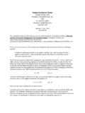
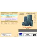
5 The Siliconix2N4340, J202, and SST202 exhibit typical goss = 2 mS atVDS = 20 V. These devices in the circuit of Figure 4 willprovide a current source adjustable from 5 mA to mAwith internal impedance greater than 2 MW at Siliconix part types such as the 2N4392, J112, andSST112 can provide 10 mA or higher +30 VFigure current Source RS = 1 MWRS = 1 MWRS200 W (Optional)Instead of the adjustable resistor, the JFETs can be put inIDSS range groupings with an appropriate RS resistorselected for each group. This method is common in highvolume cascade circuit of Figure 5 provides a currentadjustable from 2 mA to mA with internal resistancegreater than 10 +30 VDSQ2Q1100 W(Optional)RSQ1 = 2N4340, J202, SST202Q2 = 2N4341, J304, SST304RS = 1 MWFigure FET current SourceAN103 Siliconix10-Mar-97 3CR470CR430CR390CR360CR330CR300CR270CR24 0CR220CR200CR180CR160 SST/J504 SST/J503 SST/J502J501J500 Part Regulator current (mA)Figure Series current Regulator RangeTO-18 2-LeadPackageJ = TO-226AA 2-Lead PackageSST = TO-236 (SOT-23)
6 PackageIFVFSST/J510 SST/J509 SST/J508 SST/J507 SST/J506 SST/J505 SST/J511 Standard Two-Leaded DevicesSiliconix offers a special series of two-leaded JFETs witha resistor fabricated on the device, thus creating a "10% current range. Devices are available in ranges mA (CR160) to mA (CR470).For designs requiring a "20% current range, Siliconixoffers devices rated from mA typical (J500) mA typical (J511) in a two-leaded TO-226A (TO-92)package. The SST502 series is available in surface mountTO-236 (SOT-23).Each of these two-leaded devices can be used to replaceseveral typical 6 shows the current ranges of these two deviceseries. Further information is contained in the individualdata sheets appearing elsewhere in this data book or fromSiliconix CR160 series features guaranteed peak operatingvoltage minimum of 100 V with a typical of 180 V.
7 TheJ500 series features 50 V minimum with a typical of100 V. The lower current devices in both series provideexcellent current regulation down to as little as 1 Resistor SelectionAll industry JFET part types exhibit a significant varia-tion in IDSS and VGS(off) on min/max specifications anddevice-to-device the simple source biasing current source as illus-trated in Figure 1, the designer can graphically calculatethe RS which best fits the desired drain current ID. Figure7 plotting ID versus VGS over the military temperaturerange shows the resulting ID for different values of RS lines are constructed by drawing the slope of theRS desired value starting at the origin, eg.
8 RS = 2 k a convenient point on the X Y axis to mark aVGSIDof 2 k such as VGS = V and ID = , draw a straight line from this point to the intersection of this RS line and the device ID versusVGS will be the operating ID. In this example, the result-ing ID = mA at TJ = 25 C. The intercepts of the TJ= 55 C and 125 C show the minimal variation note that JFETs have a ID current where there is nochange with temperature variation. To achieve this 0TC,the VGS voltage (ID x RS) is approximately:VGS(0TC) ] VGS(off) V(11)AN103 4 Siliconix10-Mar-97 Figure Typical Transfer 2 Gate-Source Voltage (V) Drain current (mA)IDVDS = 4 to 20 V2N4339 maxSST/J202 (lowend) = 55 C125 CRS = k1 k2 k5 k10 k20 k25 CFigure Biased Drain- current vs.
9 Source Source Resistance (kW) Drain current (IDA)mVDD = 5 to 30 VTJ = 25 C except as noted101100TJ = 55 C125 C2N/PN4119 ASST4119 Max2N/PN4118 ASST4118 Max2N/PN4119 ASST4119 Min2N/PN4118 ASST4118 Min2N/PN4117 ASST4117 Min2N/PN4117 ASST4117 Source Biased Drain- current vs. Source Source Resistance (kW) Drain current (mA)ID1 VDD = 4 to 20 VTJ = 25 C except as = 55 C125 CSST/J202 Max2N4338 MaxSST/J202 Min2N4339 MinSST/J201 MaxSST/J2012N4338 C2N4339 Max25 CAN103 Siliconix10-Mar-97 5 Choosing the Correct JFET for SourceBiasingEach of the Siliconix device data sheets include typicaltransfer curves that can be used as illustrated in Figure popular devices are ideal for source biased cur-rent sources covering a few mAs to 20 mA.
10 To aid the de-signer, the devices in Table 1 have been plotted to showthe drain current , ID, versus the source resistance, RS, inFigures 8, 9, and 10. Most plots include the likely worstcase ID variations for a particular RS. For tighter currentcontrol, the JFET production lot can be divided intoranges with an appropriate resistor selection for 1: Source Biasing Device RecommendationsPracticalCurrentRange ID(mA)Through-HolePlastic DeviceSurfaceMountDeviceMetal 10J112 SST1122N4392 55 Source Resistance (kW) Drain current (IDA)m11 Figure Source Biased Drain- current vs. Source Resistance10 RSVDD = 5 to 30 VTJ = 25 C except as noted125 C2N4393,SST/J113 MaxMid2N4392,SST/J112 Min 2N4392,SST/J112 Min 2N4393 = 25 C