Transcription of LED Constant Current Source Scheme - ON …
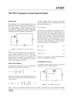
1 Theory of Operation Prepared by: Mark Scholten Senior Applications Engineer The LM317L wants to see V between its VOUT pin But what if a series/parallel combination of LEDs is and the Vadj pin, and it will do whatever it can to keep that wanted? The following circuit works fine, assuming that voltage differential between them. So if a resistor is put in there are not large variations in the forward voltage drop of series with the output, and the Vadj pin is connected to the the LEDs. There could be a problem however if one of the load side of the sense resistor, a Current Source is set up strings opens up for some reason.
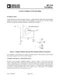
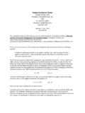
2 The LEDs that remain which follows Equation 1: would have 50% more Current flowing through them, which could cause them to be driven too hard and fail. So how does one get around this problem? IOUT + (Approximately) (eq. 1). Rsense VIN VOUT IOUT. LM317L. Rsense VIN VOUT IOUT LED1 LED4 LED7. LM317L. Rsense Vadj Rload LED2 LED5 LED8. Vadj LED3 LED6 LED9. Figure 1. Figure 3. In order to set up a Constant Current Source for an LED. string, the same circuit can be used by simply substituting The following circuit takes care of this issue by splitting Rload with an LED string, as shown below.
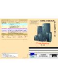
3 Up the Current sense resistor into three resistors, one for each leg of the LED string. The Current through any one of the VIN VOUT IOUT LED strings is set by Equation 2: LM317L. Rsense V ) Vsat LED1 IOUT + (Approximately) (eq. 2). R1. Vadj LED2. LED3. Figure 2. Semiconductor Components Industries, LLC, 2003 1 Publication Order Number: January, 2003 Rev. 0 AND8109/D. AND8109/D. VIN VOUT. LM317L. Vadj Q1 Q2 Q3. R4 R5 R6. Rsense1 MPS2222 Rsense2 MPS2222 Rsense3 MPS2222. LED1 LED4 LED7. LED2 LED5 LED8. LED3 LED6 LED9. Figure 4. When the circuit operates properly and all the LEDs are the sense resistor for that leg won't have any voltage across running, the three sense resistors have about V across it, turning off' the transistor and disconnecting its sense them, which turns the transistor switches on'.
4 This connects resistor from the Vadj pin. Therefore, the other two LED. all three sense resistors back to the Vadj pin allowing the strings are unaffected by the fault. This same Scheme can be proper Current to go through each leg. If one string opens up, expanded to accommodate as many LED strings as needed. ON Semiconductor and are registered trademarks of Semiconductor Components Industries, LLC (SCILLC). SCILLC reserves the right to make changes without further notice to any products herein. SCILLC makes no warranty, representation or guarantee regarding the suitability of its products for any particular purpose, nor does SCILLC assume any liability arising out of the application or use of any product or circuit, and specifically disclaims any and all liability, including without limitation special, consequential or incidental damages.
5 Typical parameters which may be provided in SCILLC data sheets and/or specifications can and do vary in different applications and actual performance may vary over time. All operating parameters, including Typicals must be validated for each customer application by customer's technical experts. SCILLC does not convey any license under its patent rights nor the rights of others. SCILLC products are not designed, intended, or authorized for use as components in systems intended for surgical implant into the body, or other applications intended to support or sustain life, or for any other application in which the failure of the SCILLC product could create a situation where personal injury or death may occur.
6 Should Buyer purchase or use SCILLC products for any such unintended or unauthorized application, Buyer shall indemnify and hold SCILLC. and its officers, employees, subsidiaries, affiliates, and distributors harmless against all claims, costs, damages, and expenses, and reasonable attorney fees arising out of, directly or indirectly, any claim of personal injury or death associated with such unintended or unauthorized use, even if such claim alleges that SCILLC was negligent regarding the design or manufacture of the part. SCILLC is an Equal Opportunity/Affirmative Action Employer.
7 PUBLICATION ORDERING INFORMATION. Literature Fulfillment: JAPAN: ON Semiconductor, Japan Customer Focus Center Literature Distribution Center for ON Semiconductor 2 9 1 Kamimeguro, Meguro ku, Tokyo, Japan 153 0051. Box 5163, Denver, Colorado 80217 USA Phone: 81 3 5773 3850. Phone: 303 675 2175 or 800 344 3860 Toll Free USA/Canada Email: Fax: 303 675 2176 or 800 344 3867 Toll Free USA/Canada ON Semiconductor Website: Email: For additional information, please contact your local N. American Technical Support: 800 282 9855 Toll Free USA/Canada Sales Representative.
8 AND8109/D. 2.