Example: bachelor of science
The mesh-current method - Iowa State University
EE 201 mesh-current method – 11 The mesh current method 1. Identify all of the individual meshes in the circuit. 2. Assign a mesh current to each mesh. Identify meshes in which the current is known because there is a current source in an outside branch of the mesh. 3. Assign voltages to all of the elements in the meshes with unknown currents. 4.
Tags:
Information
Domain:
Source:
Link to this page:
Documents from same domain
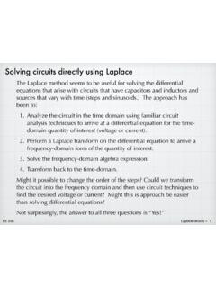
Solving circuits directly using Laplace
tuttle.merc.iastate.eduAnalyze the circuit in the time domain using familiar circuit analysis techniques to arrive at a differential equation for the time-domain quantity of interest (voltage or current). 2. Perform a Laplace transform on the differential equation to arrive a ... C in the RLC circuit below. The input is a step function, v i ...
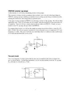
pspice op amp - Iowa State University
tuttle.merc.iastate.eduThis tutorial is written with the assumption that you know how to do ... So it looks like the uA741 model has the potential to be a reasonably accurate PSPICE op amp

How Millennials Can Get Rich Slowly
tuttle.merc.iastate.eduHow Millennials Can Get Rich Slowly William J. Bernstein ©2014 . Would you believe me if I told you that there’s an investment strategy that a seven-year-old could ... and vigor, your retirement options may well range between moving in with your kids and sleeping under a bridge in the rain.
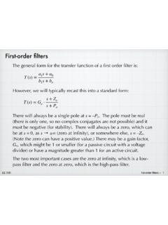
First-order filters - Iowa State University
tuttle.merc.iastate.eduFirst-order filters The general form for the transfer function of a first order filter is: T(s) = G o ... Use the standard definition for cut-off frequency, which is the frequency at which the magnitude is down by from the value in the pass-band. For our low-pass function, the pass band is at low frequencies, and the ...

Basic PMOS structure - Iowa State University
tuttle.merc.iastate.eduohmic or linear v GS < V T v DS < v GS – V T i D = K[v GS – V T]2 saturation Summary of PMOS equations K = 1 2 μCox W L VT < 0 Note the equations are identical to the NMOS equations. For a PMOS, v GS and v DS are both negative and the current flows from source to drain.
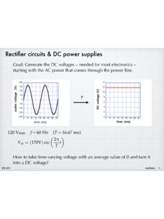
Rectifier circuits & DC power supplies
tuttle.merc.iastate.eduNov 01, 2015 · Rectifier circuits & DC power supplies Goal: Generate the DC voltages – needed for most electronics – starting with the AC power that comes through the power line.? 120 V RMS 9DF=( 9)sin 7 W f = 60 Hz (T = 16.67 ms) How to take time-varying voltage with an average value of 0 and turn it into a DC voltage?
Thevenin equivalent circuits - Iowa State University
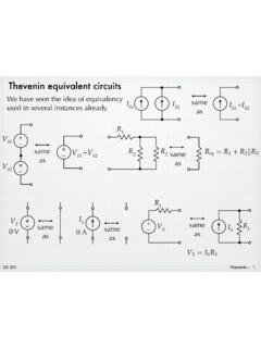
tuttle.merc.iastate.eduJun 10, 2014 · The open-circuit voltage / short-circuit current approach can be used to calculate the Thevenin equivalent for a known circuit. Consider the circuit from slide 4: + – V S R 1 R 2 I S 9V 6 mA 1.5 k! 3 k! Open-circuit voltage – Use whatever method you prefer. We’ll use node voltage in this case. + – V S R 1 R 2 I S v a + – v oc YRF= YD ...

Series and parallel combinations
tuttle.merc.iastate.eduEE 201 series/parallel combinations – 12 Breaking down networks using series and parallel R 3 R 4 R 5 R eq R 2 But not all circuits are simple R 1 combinations of series or parallel resistors. The initial example circuit clearly has some things that are in series and some elements that have a parallel-type connection.
superposition - Iowa State University
tuttle.merc.iastate.eduEE 201 superposition – 2 2va + 6vb = 2V 8va 2vb = 36V Solving gives: v a = 5 V, v b = 2 V 8v a 2v b = 0 2v a + 6v b = 2V Solving gives: and 2v a + 6v b = 0 8v a 2v b = 36V A math problem: Mathematically, we can solve the simultaneous equations a piece at a
npn Bipolar Junction Transistor - Iowa State University
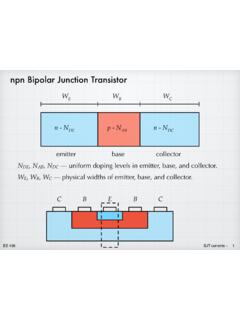
tuttle.merc.iastate.edujunction — very surprising! EE 436 BJT currents – 6 The electron current in the base is determined by the boundary ... External (terminal) currents. All currents depend on V BE in exactly the same way. Although it is a messy exponential, they …
Related documents

Solving Circuits by Mesh Analysis Example Problem
www2.seas.gwu.eduSolving Circuits by Mesh Analysis Example Problem ECE 1020 Prof. Ahmadi . Allan Guan . Problem Solve for all the currents and voltages in this circuit . R1 R3 R6 R4 R2 R5 R7 Vs Allan Guan . R1 R3 R6 R4 R2 R5 R7 Vs Step 1 Assign the mesh currents. Since there are 3 loops, we will assign 3 mesh currents. i 1 . i. 2 . i. 3

Basic circuit analysis - City U
cktse.eie.polyu.edu.hkMesh analysis Step 1: Define meshes and unknowns Each window is a mesh. Here, we have two meshes. For each one, we “imagine” a current circulating around it. So, we have two such currents, I1 and I2 — unknowns to be found. Step 2: Set up KVL equations Step 3: Simplify and solve which gives I1 = 6 A and I2 = 4 A. Once we know the mesh ...

Nodal and Loop Analysis - Waterloo Maple
www.maplesoft.comThe method behind mesh analysis is to examine the mesh in terms of the voltages of each element and express that with the mesh currents. Using Ohm's law , we can express the voltage across as . Use this approach across a circuit applying KVL to find the mesh equations, then you can use these equations to solve for unknown current.

SOME BASIC CONCEPTS OF ENGINEERING ANALYSIS
ocw.mit.eduSome basic concepts of engineering analysis. ... -150 • 16x 16 MESH-200-DISPLACEMENT DISTRIBUTION ALONG DC OF PINCHED CYLINDRICAL SHELL-0.2 • 16x 16 MESH Mil ""= 0.1 ~ C BENDING MOMENT DISTRIBUTION ALONG DC OF PINCHED CYLINDRICAL SHELL 1-7. SoBle basic concepts 01 engineering analysis I

Tutorial: Modal Analysis with Altair OptiStruct / HyperMesh
altairuniversity.comModal analysis is typically a free or constrained model. A free analysis doesn’t require constraints but will generate rigid body modes. You can avoid extracting these using variables on the EIGRL card. Modeling process Mesh components and assign properties Define constraints (if desired) and modal extraction load collector

Circuit Analysis using the Node and Mesh Methods
ocw.mit.educircuit analysis is to derive the smallest set of simultaneous equations that completely define the operating characteristics of a circuit. In this lecture we will develop two very powerful methods for analyzing any circuit: The node method and the mesh method. These methods are based on the systematic application of Kirchhoff’s laws.
![Abstract arXiv:2012.09760v3 [cs.CV] 15 Jun 2021](/cache/preview/3/9/2/7/b/7/3/8/thumb-3927b738f3aaf55413e1b633ba580258.jpg)
Abstract arXiv:2012.09760v3 [cs.CV] 15 Jun 2021
arxiv.orgduct analysis on the input features, and discover that high-resolution image features are beneficial for transformer to regress 3D coordinates of body joints and mesh vertices. 3.2. Multi-Layer Transformer Encoder with Pro-gressive Dimensionality Reduction Since we need to output 3D coordinates, we cannot

UniFi AC Mesh Datasheet - Ubiquiti
dl.ui.comBoth UniFi AC Mesh models provide wireless coverage for a street fair in a city plaza. Use Cases Mesh Multi-Hop A large outdoor area, such as a park with minimal infrastructure, can take advantage of a mesh network comprised of the UniFi AC Mesh models. Omnidirectional Coverage, Indoors or Outdoors The UAP-AC-M includes adjustable

Space Truss and Space Frame Analysis - Rice University
www.clear.rice.edu10 Space Truss and Space Frame Analysis 10.1 Introduction One‐dimensional models can be very accurate and very cost effective in the proper applications. For example, a hollow tube may require many thousands of elements to match its geometry, even though you …