Transcription of The Ring Oscillator
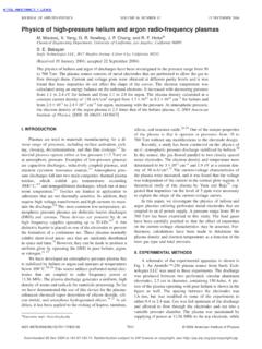
1 10 FALL 2019 IEEE SOLID-STATE CIRCUITS MAGAZINE A CIRCUIT FOR ALL SEASONSB ehzad RazaviThe Ring OscillatorRRing oscillators are commonly used in many systems because of their wide tuning range, compact layout, and ability to generate multiple phases. These advantages over inductance capacitance (LC) oscillators come at the cost of phase concept of an Oscillator con-sisting of gain stages in a ring can be traced to the vacuum-tube era. For example, in his 1953 patent, Gallay presented the structure shown in Figure 1, where nine triodes form an oscillating loop.
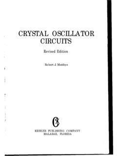
2 The grid (G), cath-ode (C), and anode (A) of a triode can be visualized as the gate, source, and drain, respectively, of a MOSFET. CMOS ring oscillators began to ap-pear in communication circuits in the late 1980s [2], [3]. In this article, we study single-ended and differen-tial ring topologies and analyze their design StructureIn its simplest form, a ring Oscillator comprises N gain stages in a loop, with negative feedback at low fre-quencies to avoid latch-up. If each stage inverts, then N must be odd (Figure 2). A rising edge at a node within the loop travels through N inverters and returns as a falling edge, forming one half of the oscil-lation period T0.
3 Thus, T0 is equal to ,NT2D where TD denotes the large-signal gate inverter-based ring shown in Figure 2 merits three remarks. First, since the delay of an inverter falls as the supply voltage VDD increases, the oscillation frequency f0 is inverse -ly proportional to VDD. This supply sensitivity, KVDD, proves serious as noise on VDD directly modulates the output frequency. Second, for a total load capacitance of CL at each node in Figure 2, the average power drawn from VDD is approximately equal to .NfCVL02DD Third, an N-stage ring provides N output phases with a minimum separation of TD seconds or [/()]()/TNTN22 DDrr= rad, but, due to the inversion in each stage, the actual phase difference is /Nrr-+.
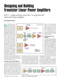
4 The problem of supply noise can be greatly alleviated through the use of differential rings. In an imple-mentation such as the one shown in Figure 3, we prefer that the differen-tial pairs experience nearly com-plete switching and, hence, produce a single-ended voltage swing equal to .IRDSS To this end, we select these transistors wide enough so that, with an input voltage difference of ,IRDSS one transistor turns off. However, a ring consisting of only three stages does not provide complete switch-ing because the delay through the loop is too short to allow VX and VY to reach VDD.
5 It can be shown [4] that the maximum swing is approximate-ly .IR05 DSS in this case. For reason-able supply rejection, the tail current source must operate in the satura-tion Object Identifier of current version: 18 November 2019 GCA2311111214241525262728181929203021312 29876543214849505152535455161710 FIGURE 1: The ring Oscillator described by Gallay. G: grid; C: cathode; A: anode. IEEE SOLID-STATE CIRCUITS MAGAZINE FALL 2019 11 Another advantage of differential rings is that they can provide multi-ple phases having a minimum spac-ing equal to r divided by an even number.
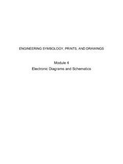
6 This is possible because a differential ring with an even N can still have negative feedback at low StudiesWe wish to quantitatively study the behavior of inverter-based and dif-ferential ring oscillators and compare their performance in terms of phase noise, power consumption, and sup-ply sensitivity. We design the two for roughly the same oscillation frequen-cy in 40-nm technology and simulate them in the slow slow corner at 75 C and with a worst-case supply voltage of V. We also include some explic-it load capacitance at each node as an estimate of the layout 4 depicts the inverter-based ring along with its waveform and phase-noise profile.
7 The circuit runs at .f2260= GHz, draws ,57Wn and ex-hibits a KVDD of GHz/V, a very large value. The phase noise falls with a slope of approximately 30 dB/dec from 100-kHz offset to 100-MHz off-set, revealing the dominance of up-converted flicker noise. The phase noise is excessively high, but it can be simply traded for power by linear scaling : if we multiply the widths of all of the transistors by M, f0 and the supply sensitivity remain constant (if the layout parasitics are scaled) while the power consumption rises by the same factor and the phase noise falls by logM10.
8 For example, selecting (/)()/WL10012040nmnmN#= and (/)()/WL10024040nmnmP#= rais-es the power to mW and reduces the phase noise at 1-MHz offset from 47 dBc/Hz to 67 dBc/Hz. Of course, the area also grows in Figure 5 are the differential ring, its waveforms, and its phase-noise profile. Operating at .f208 GHz,0= the Oscillator consumes 285 W and has a KVDD of GHz/V. We recog-nize that VX and VY do not have time to reach .V095V,DD= and the sin-gle-ended voltage swing is 270 mVpp, somewhat close to our estimate of .IR05300 DSS= mV.
9 The transistors do not enter the triode region, a point to which we return later in the context of flicker noise. The phase noise dis-plays a slope of nearly 30 dB/dec from 100-kHz offset to 1-MHz offset and 20 dB/dec thereafter. That is, flicker noise upconversion is much less pro-nounced here. Linear scaling can also be applied to the differential ring by multiplying W,12 and ISS by a factor of M and dividing RD by the same us now compare the two de-signs. Why is the supply sensitivity of the first ring so much higher than that of the second?
10 This is because the supply dependence of the delay is different in the two designs. In an in-verter, the drive strength depends on VDD; that is, the drain current and on-resistance of the transistors directly and substantially change as VDD fluctu-ates. In a differential pair, on the other hand, the load resistance is relatively constant, and only the capacitance has a slight supply dependence. Illustrated in Figure 6, this effect arises from the nonlinear drain-bulk capacitance, CDB, of M1 and M2, which varies with the common-mode voltage at X and Y and, hence, with compare the phase-noise pro-files fairly, we must normalize them to the oscillation frequency and the power consumption.