Transcription of The Slot Loaded Open Baffle Project
1 The Slot Loaded open Baffle Project by Nelson Pass Intro: ESS and the Heil Years In 1972 I had the good fortune to begin working for ESS, arriving a few weeks before they met Oskar Heil and his air motion transformer design. You can imagine the excitement that followed. The first Heil tweeter was a dipole design like an open Baffle and it operated from about 800 Hz to above 20 Khz with high accuracy and efficiency. Once the tweeter had been launched in a commercial product, thoughts turned to the notion of a low frequency version. Oskar had a design which looked like a stack of pancakes with magnets on the top and bottom and a series of parallel cones driven by rods which passed through small holes in the cones. As a concept it was workable, but it did not look like something that would be easily made.
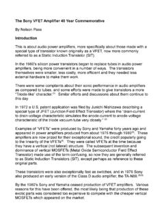
2 While Oskar continued to develop that approach I put together a prototype for the AMT-3 that used 6 regular woofers firing against flat panels in a slot loading arrangement. It looked like this: You will discern several things from the diagram, among them that I was not employed as a draftsman. What I hope you can make out is an arrangement where three woofers on each side fire into a flat surface and the pressure generated flows out the front through a vertical slot. The rear wave of the woofers is allowed to amble out rear of the enclosure. These were 8 inch woofers, which gives you an approximate sense of the scale. The purpose here, as with Oskar's transformer, was to have the air velocity at the output to be much faster than the velocity of the driving surface, in this case the loudspeaker cones.
3 The motional energy imparted to the moving air is proportional to the mass of the air times the velocity squared. The squared part means that if you triple the velocity you impart nine times as much energy, or about 9 dB worth. This raises the efficiency of the speaker quite a bit, and it improves the transient response as the apparent mass of the air moved is higher in relation to the cone mass of the drivers. The way this is accomplished is by squeezing the air through an opening narrower than the surface of the moving diaphragm of the driver. In the diagram above, the air pushed by the cones has to exit out the front of the loudspeaker through a slot opening whose surface area is only about one third that of the cone drivers, and so it goes out about three times faster than the velocity of the cones.
4 The bass performance of this system was a big surprise; I remember sitting in the lab hosting guests from Audio Magazine playing these speakers, and I noticed that their eyes were focused on a shipping box sitting on the floor. The open flaps of the box were synchronously with the warp on the vinyl LP we were playing. And it sounded great. In spite of this, the Project did not make it to market. In a phenomenon which occurs in manufacturing, it was killed when the sales manager intoned, I can't sell a speaker with no back. When such a prophecy is made, it tends to be self-fulfilling. Instead, a conventional box (which looked the same) but with two woofers on the front Baffle went to market. Oskar continued to work on his woofer, and eventually presented it in an open Baffle .
5 Since it does not seem to have been a commercial success, the sales manager was perhaps proven right, although we were both gone by then, and my early prototype speakers were torn up to salvage the 12 woofers they contained. The Up Sides They've been around forever, but open Baffle enclosures have a few charms that keep them semi-popular. First off, they are very easy to build. Anyone who can manage a hand held saber saw can make one out of a piece of plywood. There is no exact measuring or tight joint fitting. At a minimum, they are not allowed to fall over, and other improvements are optional. Second, they are free of many of the internal resonance issues that have to be considered with an enclosed box. The rear wave created by the loudspeaker doesn't bounce around the interior of the enclosure, altering the fundamental resonance and creating a host of additional resonant effects.
6 These higher frequency resonant waves partially make their way back out to the front through the cone or any opening. They are not usually wanted. Third, because the back wave is free to illuminate the wall behind the speaker and also the rest of the room through reflection, you get a very spacious acoustic effect that works very well if the room is big enough and the placement of the speakers is done carefully. This effect is very important to open Baffle fans, and certainly was not lost on Dr. Bose many years ago. It is also an important feature of most electrostatic and ribbon designs, and of course the fine products of Magnepan. The Down Sides There are two downsides to open baffles. Because the rear wave of the driver is free to wander, at low frequencies it comes around to visit the front of the loudspeaker, and being out of phase, cancels the front wave to a varying extent.
7 As a result, open Baffle designs have less deep bottom end, depending on their size. In general, the low frequency response is an inverse proportion to the dimensions of the Baffle surface. Twice the size, one more octave of bass. This factor often leads to the second major downside, humorously known as the WAF, or wife acceptance factor. Good bottom end from an open Baffle usually means a very large Baffle , more than most living rooms will tolerate. It also means the Baffle needs to be at a distance from the rear wall. I have made baffles out of 4 ft by 8 ft sheets of plywood, and they have delivered pretty good bass without equalization. For such a large Baffle the question is not only whether they will fit in your space, but at some point you start to notice that you are no longer effectively listening to that rear wall illumination, as it is being blocked by the baffles.
8 In this case, you might simply try mounting the drivers in the wall. And some people do. The Front and Rear Sides There is something important to note about the diagram of that AMT-3 prototype. In the original Heil dipoles, there is symmetry between the front and back waves, specifically the air coming out the back is squeezed to the same velocity as the air in front. In this regard they are true dipoles. In the AMT-3 prototype, this is not the case. The air coming out the front is squeezed at a ratio of about 3 to 1. The rear wave not so much. Remembering that the motional energy is proportional to the square of the velocity, we expect more energy out the front than the back. The response is not symmetric the rear wave that wants to come around and cancel at bass frequencies is not as strong as the front wave, and its ability to cancel is diminished.
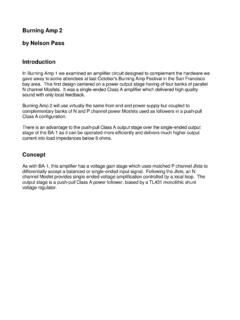
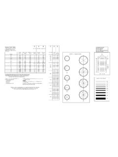
9 This is the raison d'etre of the slot Loaded open Baffle greater velocity out the front and less out the back. After about thirty-eight years, I decided to recreate the vision of that original prototype. In the summer of 2010 I had Roth Wiedrick helping me out, and he began construction of a modified version which he finished the following summer. Here is a diagram showing how this woofer is laid out: As an aid to understanding, I have highlighted the direction of air motion in this system with green arrows. The woofers are wire in phase and move toward and away from each other squeezing the air between them, and the pressure makes the air flow fast out the front. The air in back is not squeezed, and so flows more slowly out the rear. It's pretty simple stuff. The Baffle surface is made of MDF and measures about 30 inches high by 36 inches wide.
10 The six woofers are mounted in a chamber formed by laminating five layers of inch particle board, and are arranged to squeeze the air out a front slot inches wide and having about one third of their combined piston area. The edges of the slot are rounded to reduce turbulence. The eight-inch woofers are wired in either three in series, two in parallel to form a 12 ohm load, or three parallel, two in series to form 5 ohms. Because the wiring is slightly easier, I chose the 12 ohms, but if you are considering using a passive crossover here, you would definitely go for the 5 ohm arrangement for level matching. We placed another Baffle on top of this, adding another 30 inches of height and mounted a Lowther PM6A at 36 inches height. None of the dimensions or construction details are critical.