Transcription of Thevenin equivalent circuits - Iowa State University
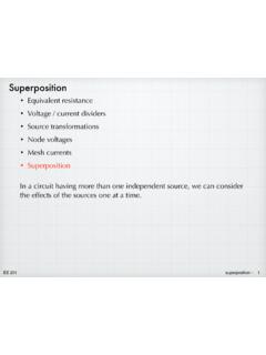
1 EE 201 Thevenin 1 Thevenin equivalent circuitsWe have seen the idea of equivalency used in several instances + VSR1same as96=,65 IS0 Asame asVS0 Vsame as+ + VS1VS2+ VS1 +VS2same assame as5HT=5 +5 5 R1R2R3IS1IS2IS1 +IS2same asEE 201 Thevenin 2 The behavior of any circuit , with respect to a pair of terminals (port) can be represented with a Thevenin equivalent , which consists of a voltage source in series with a terminals (two nodes) = port+ VThRThThevenin equivalentsomecircuitRLload+ vRL+ VThRThRLload+ vRLNeed to determine VTh and RTh so that the model behaves just like the 201 Thevenin 3 Norton equivalentINRN somecircuitload+ vRLload+ vRLIdeas developed independently ( Thevenin in 1880 s and Norton in 1920 s). But we recognize the two forms as identical because they are source transformations of each other. In EE 201, we won t make a distinction between the methods for finding Thevenin and Norton.
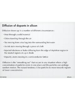
2 Find one and we have the other.+ VThRThINRN97K=,157K57K=51EE 201 Thevenin 4 Example+ VSR1R2IS+ VThRTh9V6 k!3 k!12 V1 k!RLRLRviP1 ! mW10 ! mW100 ! mW1 k! mA36 mW10 k! mW100 k! mWAttach various load resistors to the original circuit . Do the same for the equivalent circuit . For each load resistance, calculate the load voltage (and current and power) for each of the circuits . The results are identical. In terms of the load that is attached at the port, the two circuits are indistinguishable. Check it 201 Thevenin 5 Determining the Thevenin (or Norton) componentsHow to find VTh and RTh?Need two components, so two measurements or calculations should suffice. Use two different load equations, 2 unknowns:57K=5 5 (Y Y )5 Y 5 Y 97K=Y Y (5 5 )5 Y 5 Y Y =5 57K+5 97KY =5 57K+5 97K+ VThRThR2load+ v2+ VThRThR1load+ v1unknowncircuitR2load+ v2unknowncircuitR1load+ v1EE 201 Thevenin 6 More directly: open- circuit voltage, short- circuit currentunknowncircuit+ voc1.
3 Leave port open-circuited. (RL , iL = 0) Measure open- circuit voltage.+ VThRTh+ vocvoc = VThopen- circuit voltage is a direct measure of Short the output port. (RL = 0, vL = 0) Measure short- circuit current .+ VThRThiscLVF=97K57K57K=97 KLVF=YRFLVFNote, that isc can also be interpreted as a direct measurement of IN: isc = 201 Thevenin 7 Calculating Thevenin equivalentThe open- circuit voltage / short- circuit current approach can be used to calculate the Thevenin equivalent for a known the circuit from slide 4:+ VSR1R2IS9V6 k!3 k!Open- circuit voltage Use whatever method you prefer. We ll use node voltage in this case.+ VSR1R2 ISva+ vocYRF=YD 96 YD5 +,6=YD5 YD=96+5 ,6 +5 5 = 9+( . N )( P$) + . N . N = 12 VVTh = voc = 12 201 Thevenin 8 Short- circuit current Use whatever method you prefer. We ll use node voltage in this case.
4 But proceed carefully the short circuit introduces some unusual wrinkles into the circuit + VSR2 ISisca: Because of the short circuit , va = 0!b: Because of the short, vR2 = 0 and iR2 = 0. So R2 plays no role and can be + VSIS iscisc = iR1 + IS=96 YD5 +,6=965 +,6= 9 . N + P$= P$57K=97 KLVF= 9 P$= N EE 201 Thevenin 9+ VThRThINRN12 V1 k!1 k!12 mATheveninNortonIf the circuit consists of independent sources and resistors only, then the Thevenin resistance can also be found by de-activating the independent sources and finding the equivalent resistance as seen from the the sources=5 5 =( . N ) ( N )= N Alternate method for RThEE 201 Thevenin a voltmeter to measure the open- circuit voltage at the port of the circuit : voc = VTh. a short circuit across the output and use an ammeter to measure the short- circuit current : isc = IN.
5 RTh = VTh / measure VTh and RThNote that shorting the output may not always be practical. For example, some devices may have over- current protection circuitry that prevents large short- circuit currents from flowing. Or the device might not be able to handle the large current that might flow when the output is shorted without being damaged. In those a voltmeter to measure the open- circuit at the port of the circuit : voc = VTh. a load resistance, RL that is small enough so that an appreciable current is flowing. Measure the resulting load voltage, vL. 57K=5/ YRFY/ EE 201 Thevenin whatever techniques are appropriate, calculate the open- circuit voltage at the port of the circuit : voc = VTh. a short circuit across the output. Using whatever techniques are appropriate, calculate the short- circuit current : isc = IN. RTh = VTh / calculate VTh and RThAlternate method (for circuits that consist only of independent sources and resistors).
6 Whatever techniques are appropriate, calculate the open- circuit voltage at the port of the circuit : voc = VTh. all independent sources. Calculate the equivalent resistance as seen from the port. (If dependent sources are present in the circuit , the test generator method can be used to find equivalent resistance. See the equivalent resistance notes to review the test generator technique.)EE 201 Thevenin 12 Example 1R1R2R3 ISFind the Thevenin and Norton equivalents of the circuit at right, with the port as + 6 k!1 k!3 k!24 mAFind voc. Start with a current = 5 +5 5 + 5 +5 ,6= + + + ( P$)= . P$YRF=L5 5 =( . P$)( N )= . 9 VTh = voc = VFind isc. Note that R3 is shorted out. Use a current divider 5 5 + 5 ,6= + ( P$)= . P$IN = isc = mAEE 201 Thevenin 13+ k! V57K=97 KLVF= . 9 . P$= . N k! mAAlternatively, we could use the short-cut method to find RTh.
7 De-activating the current source:R1R2R3 Req5HT=5 (5 +5 )=( N ) ( N + N )= . N EE 201 Thevenin 14 Example 220 k! k! k! k! k! k!+ R1R2R3R4R5R6 VSFind the Thevenin and Norton equivalents of the circuit at left, with the port as voc. Use mesh current method.+ R1R2R3R4R5R6VS+ vociaib96 Y5 Y5 Y5 = Y5 Y5 Y5 Y5 = 96 5 LD 5 (LD LE) 5 LD= 5 (LD LE) 5 LE 5 LE 5 LE= (5 +5 +5 )LD 5 LE=965 LD (5 +5 +5 +5 )LE= Insert values and solve: ib = = ib R5 = 201 Thevenin 15+ R1R2R3R4R6 VSiscFind isc. Note that R5 is shorted out by the short equivalent resistance to find +5 +5 (5 +5 )= . N L6=9656= . P$Use current divider to find 5 +5 5 +5 + 5 L6isc = mA+ k! k! mA57K=97 KLVF= . 9 . P$= . N EE 201 Thevenin 16 Alternatively, we can use the short-cut method to find [5 +5 +5 (5 +5 )]= k!EE 201 Thevenin 17 Example 3+ R1R2R3R4R5 VSISFind the Thevenin and Norton equivalents of the circuit at right, with the port as V15 !
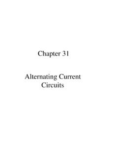
8 4 A30 !20 !30 !15 !+ R1R2R3R4R5 VSIS +vocabFind voc. Use node +L5 +,6=L5 96 YD5 =YD5 +YD YE5 L5 =L5 +L5 YD YE5 +96 YE5 +,6=YE5 +5 5 +5 5 YD 5 5 YE=96 5 5 YD+ +5 5 +5 5 YE=96+5 ,6solve: va = 20 V, vb = 40 V. " voc = vb = 40 VEE 201 Thevenin 18+ R1R2R3R5 VSISiscFind isc. Use node voltage, again. Note that R4 is shorted out (so ignore it) and node b is shorted to ground, vb = +L5 +,6=YD YE5 +96 YE5 +,6=YD5 +965 +,6 Need =L5 +L5 96 YD5 =YD5 +YD5 YD=96 +5 5 +5 5 = VLVF= . 9 + 9 + $= . $+ ! !40 A57K= 9 . $= . EE 201 Thevenin 19 Maximum power transferNow that we have the ability to model any circuit using a simple Thevenin (or Norton) equivalent , we can answer another important question: How much power can a given circuit supply to an attached load?Start with the Thevenin equivalent and determine the load resistance that would lead to the maximum amount of power being dissipated in the load.
9 + VThRThRLload+ vRL3/=Y 5/5/=5/9 7K(5/+57K) In the usual way, find the max by setting the derivative to zero and 9 7K(5/+57K) 5/9 7K(5/+57K) = 5/+57K 5/= 5/=57 KFor maximum power to the loadSee slide 4 for an example look at power column in the table.