Transcription of EE105 – Fall 2014 Microelectronic Devices and Circuits
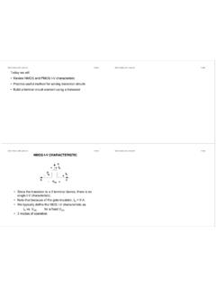
1 1 1 Lecture12-Small Signal Model-BJT EE105 Fall 2014 Microelectronic Devices and Circuits Prof. Ming C. Wu 511 Sutardja Dai Hall (SDH) 2 Lecture12-Small Signal Model-BJT Introduction to Amplifiers Amplifiers: transistors biased in the flat-part of the i-v curves BJT: forward-active region MOSFET: saturation region In these regions, transistors can provide high voltage, current and power gains Bias is provided to stabilize the operating point (the Q-Point) in the desired region of operation Q-point also determines Small-signal parameters of transistor Voltage gain, input resistance, output resistance Maximum input and output signal amplitudes Power consumption 2 3 Lecture12-Small Signal Model-BJT Transistor Amplifiers BJT Amplifier Concept The BJT is biased in the active region by dc voltage source VBE. , Q-point is set at (IC, VCE) = ( mA, 5 V) with IB = 15 A ( F = 100) Total base-emitter voltage is: vBE = VBE + vbe Collector-emitter voltage is: vCE = VCC iCRC This is the load line equation.
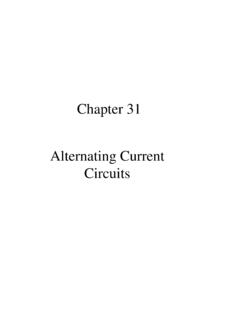
2 4 Lecture12-Small Signal Model-BJT Transistor Amplifiers BJT Amplifier (cont.) 8 mV peak change in vBE gives 5 mA change in iB and mA change in iC. mA change in iC produces a V change in vCE . If changes in operating currents and voltages are small enough, then iC and vCE waveforms are undistorted replicas of the input signal. A small voltage change at the base causes a large voltage change at collector. Voltage gain is given by: Minus sign indicates 180o phase shift between the input and output signals. Av=VceVbe= 0o=206 180o= 2063 5 Lecture12-Small Signal Model-BJT Transistor Amplifiers MOSFET Amplifier Concept MOSFET is biased in active region by dc voltage source VGS. , Q-point is set at (ID, VDS) = ( mA, V) with VGS = V Total gate-source voltage is: vGS = VGS + vgs 1 Vp-p change in vGS yields mAp-p change in iD and a 4 Vp-p change in vDS Av=VdsVgsAv=4 180o1 0oAv= Lecture12-Small Signal Model-BJT Transistor Amplifiers Coupling and Bypass Capacitors Capacitors are designed to provide negligible impedance at frequencies of interest and provide open Circuits at dc.
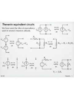
3 C1 and C2 are low impedance coupling capacitors or dc blocking capacitors whose reactance at the signal frequency is designed to be negligible. C3 is a bypass capacitor that provides a low impedance path for ac current from emitter to ground, thereby removing RE (required for good Q-point stability) from the circuit when ac signals are considered. ac coupling through capacitors is used to inject ac input signal and extract output signal without disturbing Q-point 4 7 Lecture12-Small Signal Model-BJT Transistor Amplifiers dc and ac Analysis Two Step Analysis dc analysis: Find dc equivalent circuit by replacing all capacitors by open Circuits and inductors by short Circuits . Find Q-point from dc equivalent circuit by using appropriate large-signal transistor model. ac analysis: Find ac equivalent circuit by replacing all capacitors by short Circuits , inductors by open Circuits , dc voltage sources by ground connections and dc current sources by open Circuits .
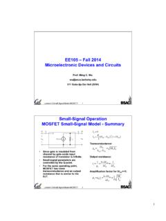
4 Replace transistor by its small-signal model Use small-signal ac equivalent to analyze ac characteristics of amplifier. Combine end results of dc and ac analysis to yield total voltages and currents in the network. 8 Lecture12-Small Signal Model-BJT Transistor Amplifiers dc Equivalent circuit for BJT Amplifier All capacitors in the original amplifier circuit are replaced by open Circuits , disconnecting vI , RI , and R3 from circuit . 5 9 Lecture12-Small Signal Model-BJT Transistor Amplifiers ac Equivalent circuit for BJT Amplifier RB=R1R2=100k 300k R=RCR3=22k 100k Capacitors are replaced by short Circuits 10 Lecture12-Small Signal Model-BJT Transistor Amplifiers dc and ac Equivalents for a MOSFET Amplifier dc equivalent ac equivalent Simplified ac equivalent Full circuit 6 11 Lecture12-Small Signal Model-BJT The slope of the diode characteristic at the Q-point is called the diode conductance and is given by: Diode resistance is given by: Small-Signal Operation Diode Small-Signal Model gd= iD vDQ point=ISVTexpVDVT#$%%&'(( IDVTrd=1gd12 Lecture12-Small Signal Model-BJT Small-Signal Operation Diode Small-Signal Model (cont.)))
5 Gd is small but non-zero for ID = 0 because slope of diode equation is nonzero at the origin. At the origin, the diode conductance and resistance are given by: gd=ISVT and rd=VTIS7 13 Lecture12-Small Signal Model-BJT Small-Signal Operation BJT Hybrid-Pi Model The hybrid-pi small-signal model is the intrinsic representation of the BJT. Small-signal parameters are controlled by the Q-point and are independent of geometry of the BJT Transconductance: Input resistance: Output resistance: gm=ICVT 40 ICr = oVTIC= ogm or o=gmr ro=VA+VCEIC VAIC14 Lecture12-Small Signal Model-BJT BJT Small-Signal Operation Small-Signal Model for pnp Transistor For the pnp transistor Signal current injected into base causes decrease in total collector current which is equivalent to increase in signal current entering collector. So the small-signal models for the npn and pnp Devices are identical!
6 IB=IB-ibiC=IC-ic= FIB Fib8 15 Lecture12-Small Signal Model-BJT Common-Emitter Amplifiers Small-Signal Analysis - ac Equivalent circuit ac equivalent circuit is constructed by assuming that all capacitances have zero impedance at signal frequency and dc voltage sources are ac ground. Assume that Q-point is already known. 16 Lecture12-Small Signal Model-BJT Common-Emitter Amplifiers Small-Signal Equivalent circuit Input voltage is applied to the base terminal Output signal appears at collector terminal Emitter is common to both input and output signals Thus circuit is termed a Common-Emitter (C-E) Amplifier. The terminal gain of the C-E amplifier is the gain from the base terminal to the collector terminal AvtCE=vcvb= gmRL RL=roRCR39 17 Lecture12-Small Signal Model-BJT Common-Emitter Amplifiers Input Resistance and Signal Source Gain Define RiB as the input resistance looking into the base of the transistor: The input resistance presented to vi is: The signal source voltage gain is: ( o+1)RERiB=vbib=r Rin=RI+RBRiB=RI+RBr AvCE=vovi=vovbvbvi=AvtCERBr RI+RBr 18 Lecture12-Small Signal Model-BJT Common-Emitter Amplifiers Rule of Thumb Design Estimate AvCE=AvtCERBr RI+RBr AvtCE AvtCE= gmRL RL=roRCR3 Typically.
7 Ro>>RC and R3>>RC AvCE gmRC= 40 ICRCICRC represents the voltage dropped across collector resistor RCA typical design point is ICRC=VCC3 AvCE 40 VCC3= help account for all the approximations and have a number that is easy toremember, our "rule-of-thumb" estimate for the voltage gain becomesAvCE 10 VCC10 19 Lecture12-Small Signal Model-BJT Common-Emitter Amplifiers Voltage Gain Example Problem: Calculate voltage gain, input resistance and maximum input signal level for a common-emitter amplifier Given data: F = 100, VA = 75 V, Q-point is ( mA, V) Assumptions: Transistor is in active region, O = F. Signals are low enough to be considered small signals. Room temperature. Analysis: gm=40IC= ()= mS r = ogm= k ro=VA+VCEIC=75V+ k RB=R1R2=160k 300k =104 k RL=roRCRL=320k 22k 100k = k RBr =104k = k 20 Lecture12-Small Signal Model-BJT Common-Emitter Amplifiers Voltage Gain Example (cont.)
8 Av= gmRLRBr RI+RBr "#$$%&''= () 1k + "#$%&'= ()= 151 Rin=RI+RBr = k vbe=viRBr RI+RBr "#$$%&'' vbe vi "#$%&'= mVCheck the rule-of-thumb estimate: AvCE 1012()= 120 (ballpark estimate)What is the maximum amplitude of the output signal: vo 151()= V11 21 Lecture12-Small Signal Model-BJT Common-Emitter Amplifiers Voltage Gain Example (cont.) Simulation Results: The graph below presents the output voltage for an input voltage that is a 5-mV, 10-kHz sine wave. Note that although the sine wave at first looks good, the positive and negative peak amplitudes are different indicating the presence of distortion. The input is near our small-signal limit for linear operation. 22 Lecture12-Small Signal Model-BJT Common-Emitter Amplifiers Dual Supply Operation - Example Problem: Find voltage gain, input and output resistances for the circuit above Given: F = 65, VA = 50 V Assumptions: Active-region operation, VBE = V, small signal operating conditions.
9 Analysis: To find the Q-point, the dc equivalent circuit is constructed. IB= AIC=65IB=241 AIE=66IB=245 A 105IB+VBE+( F+1)IB( 104)=55 104IC VCE ( 104)IE ( 5)=0 VCE= V12 23 Lecture12-Small Signal Model-BJT Common-Emitter Amplifiers Dual Supply Operation - Example (cont.) Next we construct the ac equivalent and simplify it. gm=40IC= 10 3 Sr = o40IC= k ro=VA+VCEIC=223 k Rin=RBr = k Rout=RCro= k AvCE=vovi= gmRoutR3()RinRI+Rin#$%&'(= Estimate: AvCE 10 VCC+VEE()= k)