Transcription of THRUST BEARING FAILURE PREVENTION & ANALYSIS
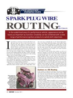
1 Crankshaft THRUST bearingsprovide a fore/aft gap-control for axial move-ment (or endplay) of thecrankshaft. These thrustbearings are located at aspecific main BEARING location, generallyat the center main or rear main, de-pending on engine design. A thrustbearing is either integrated with a spe-cific main BEARING assembly or indepen-dent of the main journal BEARING . If inte-grated, the THRUST BEARING area is presentin the form of flanges that extend fromthe front and rear of the main bearingshells. If independent, the half-moon-shaped THRUST bearings are inserted sep-arately into shallow reliefs on the frontand rear of the main BEARING saddle, andsometimes with the either case, the THRUST surfaces arelocated on each side of the designatedmain BEARING saddle and cap, intendedto maintain a specified fore/aft locationof the crankshaft, so that the crank does-n t walk too far forward or rearward.
2 Ifthere s too little THRUST clearance, thethrust BEARING surfaces can t maintain asufficient oil film and will overheat andbe destroyed, potentially allowing thecrankshaft s main journal fillets to walkinto the saddle and cap areas, quickly re-sulting in severe crank damage. If toomuch clearance exists, the much-need-ed oil film can t be maintained, eventu-ally leading to THRUST BEARING FAILURE asthe crank is THRUST forward during con-verter or clutch operation, pounding thethrust face and applying unwanted loadson the rod bearings and even pistonwrist pin/rod/piston BEARING surfaces (main bear-ings, for example) provide a slight out-of-round taper at the BEARING partingline areas to create an oil wedge thatsupports the crank journals. However, THRUST BEARING FAILURE PREVENTION & ANALYSISBYMIKEMAVRIGIAND iagnosing the root cause of a THRUST bearingfailure can be simple, but often is tricky.
3 Theeasiest course of action is to take the necessarysteps during engine assembly and installationto prevent the FAILURE from ever 2010thrust BEARING faces are generally flat,facing a flat THRUST area on the crank. Inorder for oil to be delivered to thethrust BEARING -to-crank gap, the thrustbearing will generally feature groovesthat allow oil from the radial BEARING toseep onto the THRUST BEARING face, pro-viding a film of lubrication. Some thrustbearings now feature tapered edges thathelp to promote an oil wedge. We seethis in some diesel and late-model pas-senger car a THRUST BEARING FAILURE is dis-covered, it s usually too late. The dam-age has been done, to the THRUST bearingitself and likely to the crankshaft as causes of a THRUST BEARING failurecan be traced to a single problem or acombination of , improper assembly se-lecting the wrong THRUST BEARING thick-ness, contamination during assembly,etc.
4 Can lead directly to THRUST bearingfailure. In general, though, one or moreassociated problems are usually toblame, including poor crankshaft sur-face finish, BEARING overloading or bear-ing surface transmission designs havebeen known to contribute to THRUST bear-ing FAILURE due to the greater thrustloads often in excess of 2000 lbs. Be-cause of the original equipment manu-facturers efforts to improve fuel econo-my and minimize noise, vibration andharshness, many automatic transmissionsfeature increased forward THRUST loadsthat are delivered through the addition, on manual transmissionvehicles, the use of starter lockout sys-tems (where the clutch pedal must bedepressed in order to start the engine)adds to the problem, since this placesforward pressure to the crankshaft dur-ing starting, when there s little or no oillubrication on the THRUST BEARING sur-faces. BEARING manufacturers havetried to address these OE-inherentproblems by adding a fine dispersal ofsilicon to the BEARING matrix and by de-signing angled ramp areas on thethrust faces that help to promote oildelivery to the THRUST THRUST BEARING must be able to ab-sorb forward THRUST loads that are de-livered by the transmission, torque29 August 2010 Photosillustration: Harold A.
5 Perry; images: Mike Mavrigian, Thinkstock & Wieck Mediaconverter or clutch. THRUST bearingoverloading can be caused by anynumber of problems, including poorcrankshaft surface finish (too roughand/or wavy), excessive riding of theclutch pedal, improper clutch releasebearing adjustment, excessive torqueconverter pressure or an improperlymounted front crank-driven accessory(a/c compressor, power steering pump,supercharger, etc.).If a failed THRUST BEARING is found,don t automatically blame the enginebuilder. It s very possible that the trans-mission or a transmission-related area isthe culprit. If the action of the clutch,torque converter or automatic transmis-sion hydraulic force applies constant orfrequent forward pressure on the crank-shaft, certainly the front THRUST bearingsurfaces are going to take a beating. Inthe case of a manual transmission, thiscan be caused by driv er error, as a resultof continuously riding the clutch.
6 In thecase of an automatic transmission, if theconverter constantly pushes forward,the same problem will the transmission cooler lines havebeen pinched or crimped, excesspump pressure can cause the convert-er to act like a hydraulic ram, continu-ously jamming the crank forward. Ifthe vehicle in question has undergonean engine replacement, make a pointto closely examine the transmissioncooler lines for any signs of kinking,collapse or other beginning to diagnose a thrustbearing FAILURE , instead of suspectingimproper engine assembly, first consid-er the transmission-related issues thatcan introduce undue forward loadingagainst the crankshaft. Check to see ifany external changes were made, suchas replacement of or installation of anadditional cooler. Ask the customer ifany performance modifications weremade to the transmission. Verify thatthe correct flexplate and flexplate boltswere installed, and that the transmis-sion was installed with proper align-ment to the engine block (dowel pins inplace).
7 If transmission-to-cooler pres-sure is too high, and the return linepressure is lower, inspect for restrictedcooler and cooler the case of a manual transmis-sion, also check the clutch releasebearing for proper adjustment. If therelease BEARING shows signs of extremewear and/or overheating, this is a clearindication that the driver has been rou-tinely riding the clutch pedal and/orslipping the Converter IssuesAll too often, performance enthusiastswho encounter THRUST BEARING failuretend to blame a ballooning torqueconverter. Yes, a converter body canballoon (expand) under excess pressure,which would force the flexplate andcrank forward, but this is rarely the casein a street-driven vehicle. Other con-verter-related issues should be consid-ered first, such as the wrong flexplatebolts being used, the wrong converterfor the application, improper converterinstallation or the transmission pumpgears installed CEO Dennis Madden noted inan ATRA report, although all of theseproblems will cause undue force onthe crankshaft THRUST surface, they willalso cause the same force on the pumpgears, since all of these problems willput equal force in both directions fromthe torque converter.
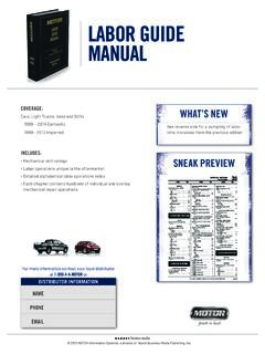
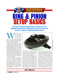
8 So any of theseconditions should also cause seriousTHRUST BEARING FAILURE PREVENTION & ANALYSISThis main BEARING features integratedthrust flanges. Note the relief groovesthat allow oil dispersion to produce anoil wedge film on the THRUST THRUST BEARING FAILURE sends contaminants throughout theengine. If not remedied quickly, the FAILURE will result in se-vere damage to the crankshaft and main THRUST cap, andfurther scoring damage to most or all internal big- block Chevy rear main cap from an early-generation454 experienced a severe THRUST BEARING FAILURE . The crank-shaft was ruined to the point of not being economically re-pairable, resulting in the purchase of a new crank. Slivers ofbearing material and crank THRUST flange surface were foundthroughout the bottom-end and sump. The crankshaft rearthrust flange was also worn down severely to a 2010 Photos: Mike Mavrigianpump damage very quickly withinminutes or from the ATRA report:The force on the crankshaft from thetorque converter is simple.
9 It s based onthe same principle as a servo piston orany other hydraulic component: Pressuremultiplied by area equals force. The pressure part is easy; it s simply theinternal torque converter pressure. Thearea is a little more tricky. The area that spart of this equation is the difference be-tween the area of the front half of theconverter and the rear half. The oil pres-sure does exert a force that tries to expandthe converter like a balloon (which is whyconverter ballooning is often blamed);however, the forward force on the crank-shaft occurs because the front of the con-verter has more surface area than the rear(the converter neck is open). This differ-ence in area is equal to the area of the in-side of the converter noted in the ATRA THRUST bearingreport, the most common example isthe THM 400 used behind a big-blockChevy. General Motors claims this en-gine is designed to sustain a force of 210lbs.
10 On the crankshaft. The inside diam-eter of the converter hub can vary to in. Therefore, the area ofthe inside of the hub can vary from sq. in.; 210 lbs. of force dividedby these two figures offers internaltorque converter pressures of 119 to100 psi, , depending on the inside diameterof the hub, it takes between 100 and 119psi of internal converter pressure toachieve a forward THRUST of 210 lbs. Thebest place to measure this pressure is atthe outgoing cooler line at the transmis-sion, because it s the closest point to theinternal converter pressure. The pres-sure gauge must be teed in, to allow thecooler circuit to flow. Normal cooler linepressure will range from 50 to 80 psi un-der a load in Drive far too low to cre-ate a forward THRUST of 210 line pressure is unequal and hy-draulic force is readily available to pushthe converter, the simple act of placingthe transmission in a forward gear canbe enough to jam the crank forward,placing a direct load against the rearthrust step for combating restrictionsin the cooler circuit is to run larger di-ameter cooler lines (to increase vol-ume and reduce pressure).