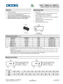
Transcription of TL43xx Precision Programmable Reference - TI.com
1 VrefInputVKAIKAP roductFolderSample &BuyTechnicalDocumentsTools &SoftwareSupport &CommunityTL431,TL431A,TL431 BTL432,TL432A,TL432 BSLVS543O AUGUST2004 REVISEDJANUARY2015TL43xxPrecisionProgram mableReference1 Features3 DescriptionTheTL431andTL432devicesare three-terminal1 ReferenceVoltageToleranceat 25 Cadjustableshuntregulators,withspecified thermal (B Grade)stabilityoverapplicableautomotive, commercial,and 1% (A Grade) outputvoltagecanbe set to anyvaluebetweenVref(approximately 2% (StandardGrade) V) and 36 V, withtwo AdjustableOutputVoltage:Vrefto 36 Vdeviceshavea typicaloutputimpedanceof . OperationFrom 40 C to 125 CActiveoutputcircuitryprovidesa verysharpturn-oncharacteristic,makingthe sedevicesexcellent TypicalTemperatureDrift (TL431B)replacementsfor Zenerdiodesin manyapplications, 6 mV (C Temp)suchas onboardregulation,adjustablepower 14 mV (I Temp,Q Temp)supplies,and TL432 Low OutputNoisedevicehasexactlythesamefuncti onalityandelectricalspecificationsas the TL431device,but has TypicalOutputImpedancedifferentpinoutsfo r the DBV,DBZ,and PK packages.
2 Sink-CurrentCapability:1 mA to 100 mABoththe TL431andTL432devicesare offeredin threegrades,with initialtolerances(at 25 C) of ,2 Applications1%,and2%,for the B, A, andstandardgrade, AdjustableVoltageand addition,lowoutputdriftversustemperature ensuresgoodstabilityoverthe entire SecondarySideRegulationin FlybackSMPS stemperaturerange. ZenerReplacementThe TL43xxCdevicesare characterizedfor operation VoltageMonitoringfrom0 C to 70 C, theTL43xxIdevicesare Comparatorwith IntegratedReferencecharacterizedfor operationfrom 40 C to 85 C, andthe TL43xxQdevicesare characterizedfor operationfrom 40 C to 125 (1)PARTNUMBERPACKAGE(PIN)BODYSIZE(NOM)SO T-23-3(3) x (5) x (8) x (8) x (8) x (1) For all availablepackages,see the orderableaddendumatthe end of the SimplifiedSchematic1An IMPORTANTNOTICEat the end of this datasheetaddressesavailability,warranty, changes,use in safety-criticalapplications,intellectual propertymattersand ,TL431A,TL431 BTL432,TL432A,TL432 BSLVS543O AUGUST2004 Contents1 Pin Configurationand Applicationsand ,TL431C, ,TL431I, ,TL431Q, Deviceand ,TL431AC, ,TL431AI, ,TL431AQ, ,TL431BC, ,TL431BI, ,TL431BQ, 1314 Mechanical,Packaging,and RevisionHistoryChangesfromRevisionN (January2014)
3 To RevisionOPage AddedApplications,DeviceInformationtable ,Pin Functionstable,ESDR atingstable,ThermalInformationtable,,Fea tureDescriptionsection,DeviceFunctionalM odes,Applicationand Implementationsection,PowerSupplyRecomme ndationssection,Layoutsection,Deviceand DocumentationSupportsection,andMechanica l,Packaging,and (July2012)to RevisionNPage (June2010)to RevisionLPage DeletedTAvaluesunderTESTCONDITIONSfor VI(dev)and II(dev)PARAMETERSin 52 SubmitDocumentationFeedbackCopyright 2004 2015,TexasInstrumentsIncorporatedProduct FolderLinks:TL431TL431 ATL431 BTL432TL432 ATL432B12348765 CATHODEANODEANODENCREFANODEANODENCTL431, TL431A, TL431B .. D (SOIC) PACKAGE(TOP VIEW)12348765 CATHODENCNCNCREFNCANODENCTL431, TL431A, TL431B .. P (PDIP), PS (SOP),OR PW (TSSOP) PACKAGE(TOP VIEW)NC No internal connectionTL431, TL431A, TL431B .. DBV (SOT-23-5) PACKAGE(TOP VIEW)12354NC CATHODEANODEREFTL431, TL431A, TL431B.
4 PK (SOT-89) PACKAGE(TOP VIEW)REFANODECATHODE Pin 2 is attached to Substrate and must beconnected to ANODE or left No internal connectionTL432, TL432A, TL432B .. DBV (SOT-23-5) PACKAGE(TOP VIEW)12354 NCANODENCREFCATHODENC No internal connectionTL431, TL431A, TL431B .. DBZ (SOT-23-3) PACKAGE(TOP VIEW)TL432, TL432A, TL432B .. DBZ (SOT-23-3) PACKAGE(TOP VIEW)NC No internal connection123 REFCATHODEANODE123 CATHODEREFANODEANODETL432, TL432A, TL432B .. PK (SOT-89) PACKAGE(TOP VIEW)REFANODECATHODEANODECATHODEANODEREF TL431 .. KTP (PowerFLEX /TO-252) PACKAGE(TOP VIEW)ANODETL431A, TL431B .. DCK (SC-70) PACKAGE(TOP VIEW)123654 CATHODENCREFANODENCNCNC No internal connectionTL431, TL431A, TL431B .. LP (TO-92/TO-226) PACKAGE(TOP VIEW)CATHODEANODEREFTL431,TL431A,TL431 BTL432,TL432A, AUGUST2004 REVISEDJANUARY20156 Pin Configurationand FunctionsPin FunctionsPINTLV431xTLV432xTYPEDESCRIPTIO NNAMEP, PSDBZDBVPKDLPKTPDCKDBZDBVPKPWCATHODE1331 1111241I/OShuntCurrent/VoltageinputREF24 188333153 IThresholdrelativeto commonanode2, 3,ANODE3526226322 OCommonpin, normallyconnectedto ground6, 7 Copyright 2004 2015,TexasInstrumentsIncorporatedSubmitD ocumentationFeedback3 ProductFolderLinks.
5 TL431TL431 ATL431 BTL432TL432 ATL432 BTL431,TL431A,TL431 BTL432,TL432A,TL432 BSLVS543O AUGUST2004 (unlessotherwisenoted)(1)MINMAXUNITVKAC athodevoltage(2)37 VIKAC ontinuouscathodecurrentrange 100150mAII(ref)Referenceinputcurrentrang e CTstgStoragetemperaturerange 65150 C(1)StressesbeyondthoselistedunderAbsolu teMaximumRatingsmay causepermanentdamageto the stressratingsonly,and functionaloperationof the deviceat theseor any otherconditionsbeyondthoseindicatedunder RecommendedOperatingConditionsis not absolute-maximum-ratedconditionsfor extendedperiodsmay affectdevicereliability.(2)All voltagevaluesare with respectto ANODE, (HBM),per ANSI/ESDA/JEDECJS-001(1) 2000V(ESD)ElectrostaticdischargeVCharged -devicemodel(CDM),per JEDEC specificationJESD22- 1000C101(2)(1)JEDEC documentJEP155statesthat 500-VHBM allowssafe manufacturingwith a than500-VHBMis possiblewith the necessaryprecautions.(2)JEDEC documentJEP157statesthat 250-VCDM allowssafe manufacturingwith a than250-VCDMis possiblewith the (1)PPWDPSDCKDBVDBZLPPKUNIT8 PINS6 PINS5 PINS3 PINSR JAJunction-to-ambientthermal851499795259 20620614052resistance C/WR JC(top)Junction-to-case(top)thermal57653 9468713176559resistance(1)For moreinformationabouttraditionaland new thermalmetrics,see theIC PackageThermalMetricsapplicationreport(S PRA953).
6 (1)MINMAXUNITVKAC athodevoltageVref36 VIKAC athodecurrent1100mATL43xxC070 TAOperatingfree-airtemperatureTL43xxI 4085 CTL43xxQ 40125(1)Maximumpowerdissipationis a functionof TJ(max), JA, and TA. The maximumallowablepowerdissipationat any allowableambienttemperatureis PD= (TJ(max) TA)/ JA. Operatingat the absolutemaximumTJof 150 C can 2004 2015,TexasInstrumentsIncorporatedProduct FolderLinks:TL431TL431 ATL431 BTL432TL432 ATL432BR2R1|z |KA(1 +( I V|z'| = IKA VKA|z | =KA(2)The dynamicimpedanceis definedas:Whenthe deviceis operatingwith two externalresistors(seeFigure21), the total dynamicimpedanceof the circuitis givenby:whichis ,TL431A,TL431 BTL432,TL432A, AUGUST2004 ,TL431C,TL432 Coverrecommendedoperatingconditions,TA= 25 C (unlessotherwisenoted)TL431C,TL432 CPARAMETERTESTCIRCUITTESTCONDITIONSUNITM INTYPMAXVrefReferencevoltageSee Figure20 VKA= Vref, IKA= 10 mA244024952550mVSOT23-3and TL432 Deviationof referenceinput616 VKA= Vref,devicesVI(dev)voltageoverfull temperatureSee Figure20mVIKA= 10 mA,range(1)All otherdevices425 Ratioof changein Reference VKA= 10 V Vref Vref/voltageto the changeinSee Figure21 IKA= 10 mAmV/V VKA VKA= 36 V 10 V 1 2cathodevoltageIrefReferenceinputcurrent See Figure21 IKA= 10 mA, R1 = 10 k , R2 = 24 ADeviationof referenceinputII(dev)currentoverfull temperatureSee Figure21 IKA= 10 mA, R1 = 10 k , R2 = Arange(1)MinimumcathodecurrentforIminSee Figure20 VKA= Figure22 VKA= 36 V, Vref= A|zKA|Dynamicimpedance(2)See Figure20 VKA= Vref, f 1 kHz,IKA= 1 mA to 100 (1)))
7 The deviationparametersVref(dev)and Iref(dev)are definedas the differencesbetweenthe maximumand minimumvaluesobtainedoverthe averagefull-rangetemperaturecoefficiento f the referenceinputvoltage Vrefis definedas: Vrefis positiveor negative,dependingon whetherminimumVrefor maximumVref, respectively,occursat the 2004 2015,TexasInstrumentsIncorporatedSubmitD ocumentationFeedback5 ProductFolderLinks:TL431TL431 ATL431 BTL432TL432 ATL432BR2R1|z |KA(1 +( I V|z'| = IKA VKA|z | =KA(2)The dynamicimpedanceis definedas:Whenthe deviceis operatingwith two externalresistors(seeFigure21), the total dynamicimpedanceof the circuitis givenby:whichis ,TL431A,TL431 BTL432,TL432A,TL432 BSLVS543O AUGUST2004 ,TL431I,TL432 Ioverrecommendedoperatingconditions,TA= 25 C (unlessotherwisenoted)TL431I,TL432 IPARAMETERTESTCIRCUITTESTCONDITIONSUNITM INTYPMAXVrefReferencevoltageSee Figure20 VKA= Vref, IKA= 10 mA244024952550mVSOT23-3and TL432 Deviationof referenceinput1434 VKA= Vref,devicesVI(dev)voltageoverfull temperatureSee Figure20mVIKA= 10 mArange(1)All otherdevices550 Ratioof changein Reference VKA= 10 V Vref Vref/voltageto the changeinSee Figure21 IKA= 10 mAmV/V VKA VKA= 36 V 10 V 1 2cathodevoltageIrefReferenceinputcurrent See Figure21 IKA= 10 mA, R1 = 10 k , R2 = 24 ADeviationof referenceinputII(dev)currentoverfull temperatureSee Figure21 IKA= 10 mA, R1 = 10 k , R2 = Arange(1)MinimumcathodecurrentforIminSee Figure20 VKA= Figure22 VKA= 36 V, Vref= A|zKA|Dynamicimpedance(2)See Figure20 VKA= Vref, f 1 kHz,IKA= 1 mA to 100 (1)))
8 The deviationparametersVref(dev)and Iref(dev)are definedas the differencesbetweenthe maximumand minimumvaluesobtainedoverthe averagefull-rangetemperaturecoefficiento f the referenceinputvoltage Vrefis definedas: Vrefis positiveor negative,dependingon whetherminimumVrefor maximumVref, respectively,occursat the 2004 2015,TexasInstrumentsIncorporatedProduct FolderLinks:TL431TL431 ATL431 BTL432TL432 ATL432BR2R1|z |KA(1 +( I V|z'| = IKA VKA|z | =KA(2)The dynamicimpedanceis definedas:Whenthe deviceis operatingwith two externalresistors(seeFigure21), the total dynamicimpedanceof the circuitis givenby:whichis ,TL431A,TL431 BTL432,TL432A, AUGUST2004 ,TL431Q,TL432 Qoverrecommendedoperatingconditions,TA= 25 C (unlessotherwisenoted)TL431Q,TL432 QPARAMETERTESTCIRCUITTESTCONDITIONSUNITM INTYPMAXVrefReferencevoltageSee Figure20 VKA= Vref, IKA= 10 mA244024952550mVDeviationof referenceinputVI(dev)voltageoverfull temperatureSee Figure20 VKA= Vref, IKA= 10 mA1434mVrange(1)Ratioof changein Reference VKA= 10 V Vref Vref/voltageto the changeinSee Figure21 IKA= 10 mAmV/V VKA VKA= 36 V 10 V 1 2cathodevoltageIrefReferenceinputcurrent See Figure21 IKA= 10 mA, R1 = 10 k , R2 = 24 ADeviationof referenceinputII(dev)currentoverfull temperatureSee Figure21 IKA= 10 mA, R1 = 10 k , R2 = Arange(1)MinimumcathodecurrentforIminSee Figure20 VKA= Figure22 VKA= 36 V, Vref= A|zKA|Dynamicimpedance(2)See Figure20 VKA= Vref, f 1 kHz,IKA= 1 mA to 100 (1)The deviationparametersVref(dev)and Iref(dev)))
9 Are definedas the differencesbetweenthe maximumand minimumvaluesobtainedoverthe averagefull-rangetemperaturecoefficiento f the referenceinputvoltage Vrefis definedas: Vrefis positiveor negative,dependingon whetherminimumVrefor maximumVref, respectively,occursat the 2004 2015,TexasInstrumentsIncorporatedSubmitD ocumentationFeedback7 ProductFolderLinks:TL431TL431 ATL431 BTL432TL432 ATL432BR2R1|z |KA(1 +( I V|z'| = IKA VKA|z | =KA(2)The dynamicimpedanceis definedas:Whenthe deviceis operatingwith two externalresistors(seeFigure21), the total dynamicimpedanceof the circuitis givenby:whichis ,TL431A,TL431 BTL432,TL432A,TL432 BSLVS543O AUGUST2004 ,TL431AC,TL432 ACoverrecommendedoperatingconditions,TA= 25 C (unlessotherwisenoted)TL431AC,TL432 ACPARAMETERTESTCIRCUITTESTCONDITIONSUNIT MINTYPMAXVrefReferencevoltageSee Figure20 VKA= Vref, IKA= 10 mA247024952520mVSOT23-3and TL432 Deviationof referenceinput616 VKA= Vref,devicesVI(dev)voltageoverfull temperatureSee Figure20mVIKA= 10 mArange(1)All otherdevices425 Ratioof changein Reference VKA= 10 V Vref Vref/voltageto the changeinSee Figure21 IKA= 10 mAmV/V VKA VKA= 36 V 10 V 1 2cathodevoltageIrefReferenceinputcurrent See Figure21 IKA= 10 mA, R1 = 10 k , R2 = 24 ADeviationof referenceinputII(dev)currentoverfull temperatureSee Figure21 IKA= 10 mA, R1 = 10 k , R2 = Arange(1)MinimumcathodecurrentforIminSee Figure20 VKA= Figure22 VKA= 36 V, Vref= A|zKA|Dynamicimpedance(2)))
10 See Figure20 VKA= Vref, f 1 kHz,IKA= 1 mA to 100 (1)The deviationparametersVref(dev)and Iref(dev)are definedas the differencesbetweenthe maximumand minimumvaluesobtainedoverthe averagefull-rangetemperaturecoefficiento f the referenceinputvoltage Vrefis definedas: Vrefis positiveor negative,dependingon whetherminimumVrefor maximumVref, respectively,occursat the 2004 2015,TexasInstrumentsIncorporatedProduct FolderLinks:TL431TL431 ATL431 BTL432TL432 ATL432BR2R1|z |KA(1 +( I V|z'| = IKA VKA|z | =KA(2)The dynamicimpedanceis definedas:Whenthe deviceis operatingwith two externalresistors(seeFigure21), the total dynamicimpedanceof the circuitis givenby:whichis ,TL431A,TL431 BTL432,TL432A, AUGUST2004 ,TL431AI,TL432 AIoverrecommendedoperatingconditions,TA= 25 C (unlessotherwisenoted)TL431AI,TL432 AIPARAMETERTESTCIRCUITTESTCONDITIONSUNIT MINTYPMAXVrefReferencevoltageSee Figure20 VKA= Vref, IKA= 10 mA247024952520mVSOT23-3and TL432 Deviationof referenceinput1434 VKA= Vref,devicesVI(dev)voltageoverfull temperatureSee Figure20mVIKA= 10 mArange(1)All otherdevices550 Ratioof changein Reference VKA= 10 V Vref Vref/voltageto the changeinSee Figure21 IKA= 10 mAmV/V VKA VKA= 36 V 10 V 1 2cathodevoltageIrefReferenceinputcurrent See Figure21 IKA= 10 mA, R1 = 10 k , R2 = 24 ADeviationof referenceinputII(dev)currentoverfull temperatureSee Figure21 IKA= 10 mA, R1 = 10 k , R2 = Arange(1)MinimumcathodecurrentforIminSee Figure20 VKA= Figure22 VKA= 36 V, Vref= A|zKA|Dynamicimpedance(2)See Figure20 VKA= Vref, f 1 kHz,IKA= 1 mA to 100 (1)))