Transcription of Torque Torque and Rotational Inertia
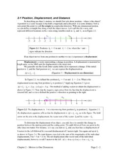
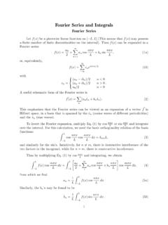
1 1 Torque and Rotational Inertia2 TorqueTorque is the Rotational equivalence of force. So, a net Torque will cause an object to rotate with an angular all Rotational motions have an axis of rotation, a Torque must be defined about a Rotational Torque is a force applied to a point on an object about the axis of size of a Torque depends on (1) the size of the force appliedand (2) its perpendicular distance from the axis of rotation(which depends both on the direction of the forceplus its physical distance from the axis of rotation).3A revolving door effect of the physical distance from the axis of rotationA force is applied to a revolving door that rotates about its center: Rank these situations based on the magnitude of the Torque experienced by the door, from largest to smallest.
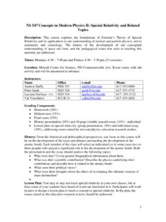
2 A < B1. B > A2. B = A3. B < AAxis of rotation4A revolving door effect of the direction of forceA force is applied to a revolving door that rotates about its center: Rank the above two situations based on the magnitude of the Torque experienced by the door, from largest to smallest. 1. D > A2. D = A3. D < AAxis of rotation5 The force component (Fcos ) that acts along a line that passes through the axis of rotation does nothing. a revolving door effect of the direction of force (components view)Axis of rotationAxis of rotation6 Perpendicular force Fsin acting at a distance of rfrom the axis of revolving door Components vs. perpendicular distance viewr rsin Component view Perpendicular distanceview rForce Facting at a perpendicular distance of rsin from the axis of rotation.
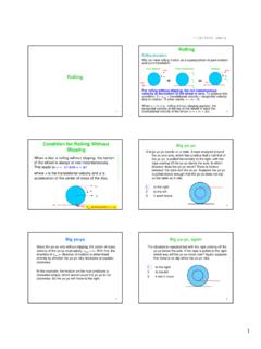
3 Notice that rsin encompasses the effects of both the physical distance and direction of short, Torque is a vectorwith magnitudegiven by: =sinrFwhere is the angle between rand (SI): NmrAxis of rotationThe directionof a Torque (counterclockwise or clockwise) is determined by the direction of rotation the Torque will cause an object to adopt from : Torque on a rodFind the Torque applied by the string on the rod shown below. string= LFTsin FTDirection: anticlockwise9 Torque due to the weight of an extended objectCenter of mass of the rodmgFor an extended object ( , one whose mass is distributed over a volume in space), the Torque due to its weight (mg) is that due to a force equal to mgacting downward at its center of of rotation10 Net Torque acting on the rod in Example 1L/2mg FT= LFTsin mg= (L/2)mg(Negative because it produces Rotational motion in the opposite direction to FT.)
4 The net torqueacting on the rod is a sum of the two torques: = FT+ mgSo, there are actually two torques acting on the rod about the hinge (labeled axis of rotation in the figure), one from the tension in the string, FT, and one from the rod s own weight, mg:11 Rotational Inertia or Moment of InertiaThe Rotational equivalence of mass is moment of inertial, I. It accounts for how the mass of an extended object is distributed relative to the axis of rotation. For a point mass mconnected to the axis of rotation by a massless rod with length r, I= the mass is distributed at different distances from the rotation axis, the moment of Inertia can be hard to calculate. The expressions for Ifor several standard shapes are listed on the next page. mrAxis of rotation1232A table of Rotational inertiaThe distribution of the mass of a rod about an axis is more spread outwhen the axis is located at the edge of the rod than when it is located at the center of parallel axis theoremIf you know the Rotational Inertia of an object of mass mwhen it rotates about an axis that passes through its center of mass, the object s Rotational Inertia when it rotates about a parallel axis a distance haway is:=+2 CMII mhxTake a ring with radius Rand mass Mas an example:xAxis of rotationI= MR2I= MR2+ MR2= 2MR214 Newton s Second Law for RotationThe equation, is the Rotational equivalent of.
5 Torque plays the role of Inertia plays the role of acceleration plays the role of the acceleration. = vvI= vvFma15 Newton s First Law for RotationAn object at rest tends to remain at rest, and an object that is spinning tends to spin with a constant angular velocity, unless (1) it is acted on by a nonzero net Torque or (2) there is a change in the way the object's mass is distributed. Based on / t= = net/ I, if either netis nonzero or if Iis changing with time, is changing with an object to remain in equilibrium, two conditions must be met.(1) The object must have no net force:(2) and no net Torque : about anyrotational v0F = v017 Hinge ForceL/2mgFHyFHxA hinge force (a vector), FH, generally exists at the hinge (usually the axis of rotation) of an hinged object at equilibriumThe figure below shows the hinge force (decomposed into x and y components) for the hinged rod discussed before.
6 By appropriately using the requirements F= 0 and = 0, we can determine both components of equilibrium exampleExample 1: Model of our lower armThis is a model of our lower arm, with the elbow being the of the lower armCenter of mass (CoM) of the lower armForce from the bisepsand trisepsHinge at our elbow joint19 Draw a free-body diagram for a horizontal rod that is hinged at one end. The rod is held horizontal by an upward force applied by a spring scale of the way along the the reading on the scale (FS) and the hinge force (FH) in terms of mg, the weight of the rod if the rod is at FHbe the hinge force, and we decompose it into FH,xand FH,yalong the x and y direction, ,yFH,xFSExample 1: Model of our lower arm20To solve for FS, we can use _____, calculated about anyrotational axis, EXCEPTfor the one that passes through the point where FSis applied because this choice will make the Torque coming from FSgo to zero (since r for that Torque would be zero) and cause FSto be eliminated from the the different possible choices for the Rotational axis, we choose the one that passes through the hinge, with the advantage being that the unknown hinge force will get eliminated from the equation.
7 Let s define clockwise to be positive, and assume that FSis upward and the rod has length L. Example 1: Model of our lower arm+ = =0242 SSFLLmgFmg = v0 FS= 2mg = v021To find the hinge force, we can applied Fx= 0 and Fy= 0 to the system. Fx= 0 FHx= 0 Fy= 0 FHy+ FS mg = 0 FHy= mg FS FHy= mg 2mg = -mgThis negative sign means that the hinge force is actually pointing down, , directed opposite to what is drawn for FHyin the 1: Model of our lower armmgL/4L/2FH,yFH,xFS22 Moving the spring scaleWhat, if anything, happens when the spring scale is moved farther away from the hinge? To maintain equilibrium:1. The magnitude of the spring-scale force The magnitude of the spring-scale force The magnitude of the downward hinge force The magnitude of the downward hinge force Both 1 and 36.
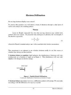
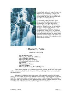
8 Both 1 and 47. Both 2 and 38. Both 2 and 49. None of the above. The drawing shows an A-shaped ladder. Both sides of the ladder are equal in length. This ladder is standing on a frictionless horizontal surface, and only the crossbar (which has a negligible mass) of the "A" keeps the ladder from collapsing. The ladder is uniform and has a mass of kg. Determine the tension in the crossbar of the 3 An A-shaped ladderSolutionDue to the symmetry of the ladder, the weight of the laddercan be taken to be acting equally at the mid-point of each side of the ladder. In addition, due to the symmetry of the problem, it issufficient to consider only one side of the Fy= 0, FN= mg/2In writing the explicit terms for = 0, we choose the axis of rotation to be at the vertex of the ladder, perpendicular to the plane facing us.
9 (2 m)(mg/2)(sin15o) + (3 m)(Tcos15o) (4 m)(FNsin15o) = 0 T = (4 FNsin15o mgsin15o)/(3cos15o) T = (2mg - mg)tan15o/3 = (14 kg)( m/s2)tan15o/3 = Nsince FN= mg/215o