Transcription of TPD12S016 PCB Layout Guidelines for HDMI ESD …
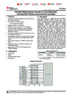
1 SLLA324 February 2012 Application Report TPD12S016 PCB Layout Guidelines for HDMI ESD Roger Liang High Volume Linear ABSTRACT TPD12S016 is a multifunction ESD protection device that integrates a HDMI compliant 55mA load switch, three level shifting buffers, and hot plug detect function along with ESD protection for all pins connected to the HDMI connector, including four pairs of high speed differential lines. This device targets the mobile sector with the QFN package and the set-top-box sector with the TSSOP package.
2 This app note discusses optimized PCB design Guidelines for both packages. With good Layout design practice, TPD12S016 can fully support data rate at and minimize PCB real estate. In addition to using differential lines, other compensation structures for parasitic capacitance are presented as well. In order to understand Layout optimization, HDMI signals are explained in detail. TPD12S016 s TSSOP and QFN packages both take advantage of the single straight line TMDS pin-outs, which allow for simple 45 angle routings. 1 Introduction TPS12S016 offers eight ultra low-capacitance ESD clamps, which allow HDMI data rates to pass through while simultaneously providing IEC61000-4-2 (Level 4) ESD protection for all pins connected to the HDMI connector. The integrated ESD circuits provide good matching between each differential signal pair (data and clock); this is an advantage over discrete ESD solutions where variations between ESD protection clamps degrade the differential signal quality.
3 TPD12S016 provides a current limited 5V output (5V_OUT) at 55mA for sourcing the HDMI power line. 5V_OUT and the hot plug detect (HPD) circuitry are controlled by the CT_HPD pin, which is independent of the level shifting buffer s control signal LS_OE. An internal node powers the CEC pin, eliminating the need for a on board supply. TPD12S016 integrates all the external termination resistors on the HPD, CEC, SCL, and SDA lines. The HPD_B port has a glitch filter to avoid false detection due to plug bouncing during HDMI connector insertion. Figure 1 shows a simplified circuit schematic and Figure 2 shows an application schematic using two GPIO for HDMI interface control. Key features and benefits of the TPD12S016 include: Supports Data Rate Built-in HDMI compliant current limiting load switch Built-in pull-up and pull-down resistors compliant with spec Built-in hot-plug-detect Match Class D and Class C pin mapping Auto direction sensing level shifting buffer with integrated pull-ups and a one-shot circuit (drives at least 750pF load).
4 1 SLLA324 February 2012 Figure 1. Circuit Schematic Figure 2. Application Schematic for HDMI controllers using two GPIO for interfacing 2 HDMI Signal Types TMDS There are four sets of high-speed Transition Minimalized Differential Signal (TMDS) lines in HDMI application, which include data lines D0 , D1 , D2 , and clock lines CLK . According to HDMI specification, CLK can reach a maximum speed of 340 MHz, with maximum data throughput reaching on the data lines. During each clock cycle, a package of 10 bits of information is exchanged on the TMDS lines. The relatively high frequency of these signals makes routing of the lines critical. There a several things to keep in mind: The number of stubs should be kept to a minimum. Trace lengths should be kept to a minimum. Special care needs to be made to match length in all these lines. 2 SLLA324 February 2012 Application Report Any significant trace length difference among the differential pairs will introduce signal skew, which could violate HDMI specification.
5 Long trace lengths can increase time delay, increase EMI radiation, and corrupt signal integrity. The high speed lines can be routed differentially or separately. If the lines are routed through a noisy environment or if they have to be routed relatively long, it may be beneficial to route them differentially and make the pair 100 with respect to each other (not with the ground plane underneath). Otherwise, 50 trace impedance can be used and made with respect to the ground plane underneath. DDC, HPD, CT_HPD/LS_OE, VCC5V/5V_OUT The display data channel lines (DDC) are made up of SDA, SCL, and CEC. These lines have internal pull-up resistors and run at 400 kHz or less. The hot plug detect (HPD) signal is a single direction signal that indicates to a transmitter the presence of a receiver connected on the line. The CT_HPD and LS_OE control lines enable the HPD scheme and level shifters respectively. They are referenced to VCCA and have internal pull-down resistors.
6 VCC5V and 5V_OUT are the input and output of the load switch respectively. High speed trace consideration is not needed in routing any of these lines. Traces to and from these pins should be routed after those from the TDMS lines are routed first. 3 RKT package considerations The RKT package is suitable for mobile applications where board space is a premium. The package length (4mm) closely matches that of the HDMI Type D receptacle footprint; placing TPD12S016 RKT close to the HDMI connector not only makes routing easy but also increases system level ESD protection robustness. In an ESD event, the bulk of the energy would be dissipated through the ESD diodes inside TPD12S016 RKT before excess energy has time to damage to other ICs on the board. Figure 3 shows the pin outs of the RKT package. Three routing layers are needed: one layer for the Transition Minimalized Differential Signal (TMDS) lines, Dx and CLK , and a pair of layers for other signal and power traces.
7 Figure 3. TPD12S016 RKT Package pin out 3 SLLA324 February 2012 An example RKT routing to a Type D receptacle pin out is discussed below. Figure 4 shows both the TPD12S016 RKT and the Type D footprint on the top layer and the TMDS lines running through vias and routed on the bottom layer. Notice that since Type D receptacles have two rows of pins and that D1 and CLK has to be routed through the bottom layer in order to minimize trace length, it is good practice to route all differential pairs the same way in order to minimize signal skew between the pairs. When routing the differential traces to the HDMI controller, keep good differential trace practices as outlined in the appendix. Figure 4. Layout of TMDS Lines Routed on the Bottom Layer Figure 5 shows routing of the non-TMDS lines. Since these do not carry high speed signals, they can be routed with flexibility. Figure 6 shows a hybrid view, combining all three routing layers. Figure 5.
8 Layout of non-TMDS Lines 4 SLLA324 February 2012 Application Report Figure 6. Layout of Hybrid Lines 5 SLLA324 February 2012 4 PW package considerations Figure 7. TPD12S016PW Package Pin Out Figure 8 shows a Layout example for the TPD12S016PW with HDMI Type A receptacle. Type C receptacle routing is done in a similar fashion; the TMDS lines would have to be brought in closer together because of the smaller pitch of the Type C receptacle. Since the PW package is larger and has no top or bottom pins on the footprint, TMDS traces can be routed straight through on the top layer and only two layers are needed for routing TMDS plus all other pins.
9 When routing TMDS lines from the HDMI transmitter, through the TPD12S016PW, and to the HDMI connector, one needs to keep differential pairs tight and width gap consistent. Minimize trace lengths and do not create angles sharper than 45 . Refer to the appendix for differential routing Guidelines . Figure 8. TPD12S016PW routing with Type A Receptacle 6 SLLA324 February 2012 Application Report 7 5 TPD12S016PW EVM Board An EVM (evaluation module) was created for testing the TPD12S016PW package. This four layer board is shown below in Figure 9. Figure 9. TPD12S016 EVM This EVM has three segments. The top segment of the Layout uses HDMI Type A connectors.
10 The middle segment has 2 HDMI Type C connectors. The connectors on the left side of the EVM are on the bottom of the board. The bottom segment is designed for user specified additional RC networks. This bottom board segment includes an HDMI Type A connector on one side and high speed traces fanned out for probe testing and loading on the other. Eye pattern testing is done for the top DUT; results are shown in Figure 10 and 11. Figure 10. Eye diagram using EVM without TPD12S016 for the TMDS Lines at 1080p, 340 MHz pixel clock, Figure 11. Eye diagram using EVM with TPD12S016 for the TMDS Lines at 1080p, 340 MHz pixel clock, SLLA324 February 2012 Skinny Traces Following HDMI compliance, differential impedance on the TMDS traces is fixed at 100 . Figure 12 shows a schematic representation of the elementary components of a lossless transmission line; in this case the differential trace is the transmission line. Shown in Equation 1, O is the characteristic impedance of the line, L is the inductance per unit length, and C is the capacitance per unit length.