Transcription of TPS543x 3-A, Wide Input Range, Step-Down Converter
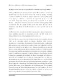
1 VINNCNCENAGNDVSENSEBOOTPHTPS5430 %IOutput Current AO--Efficiency vs Output CurrentSimplified SchematicVI= 12 VV = 5 Vf = 500 kHzT = 25 COsAo25055657585 ProductFolderOrderNowTechnicalDocumentsT ools &SoftwareSupport &CommunityReferenceDesignAn IMPORTANTNOTICEat the end of this datasheetaddressesavailability,warranty, changes,use in safety-criticalapplications,intellectual propertymattersand ,TPS5431 SLVS632I JANUARY2006 REVISEDAPRIL2017 TPS543x3-A, wide Input Range, Step-DownConverter11 Features1 WideInputVoltageRange: TPS5430 V to 36 V TPS5431 V to 23 V Up to 3-A Continuous(4-A Peak)OutputCurrent HighEfficiencyup to 95%Enabledby 110-m IntegratedMOSFETS witch with InternalCompensationMinimizesExternalPar tsCount Fixed500 kHz SwitchingFrequencyfor SmallFilterSize ImprovedLine Regulationand TransientResponseby InputVoltageFeedForward SystemProtectedby OvercurrentLimiting,OvervoltageProtectio nand ThermalShutdown 40 C to 125 C OperatingJunctionTemperatureRange Availablein SmallThermallyEnhanced8-PinSOPowerPAD Package Createa CustomDesignUsingthe TPS5430 Withthe WEBENCH PowerDesigner2 Applications Consumer.
2 Set-topBox,DVD,LCDD isplays Industrialand Car AudioPowerSupplies BatteryChargers,HighPowerLEDS upply 12-V/24-VDistributedPowerSystems3 DescriptionThe TPS543xis a high-output-currentPWMconverterthat integratesa low-resistance, the substratewiththe listedfeaturesarea high-performancevoltageerroramplifiertha tprovidestightvoltageregulationaccuracyu ndertransientconditions;an undervoltage-lockoutcircuitto preventstart-upuntilthe V; an internallyset slow-startcircuitto limitinrushcurrents;and a voltagefeed-forwardcircuitto improvethe ENApin,shutdownsupplycurrentisreducedto 18 A ,overcurrentlimiting,over-voltageprotect ionand reducedesigncomplexityandexternalcompone ntcount,theTPS543xfeedbackloopis TPS5431is intendedto operatefrompowerrailsup to 23 V. The TPS5430regulatesa widevarietyofpowersourcesincluding24 V availablein a thermallyenhanced,easyto use8-pinSOICP owerPAD providesevaluationmodulesandtheDesigners oftwaretoolto aid in quicklyachievinghigh-performancepowersup plydesignsto (1)PARTNUMBERPACKAGEINPUTVOLTAGETPS5430 HSOP(8) V to 36 V to 23 V(1) For all availablepackages,see the orderableaddendumatthe end of the ,TPS5431 SLVS632I JANUARY2006 :TPS5430 TPS5431 SubmitDocumentationFeedbackCopyright 2006 2017,TexasInstrumentsIncorporatedTableof Contents1 Pin Configurationand Applicationand Deviceand Mechanical,Packaging,and RevisionHistoryChangesfromRevisionH (April2016)to RevisionIPage AddedWEBENCH ChangedAbsoluteMaximumRatingsPH (transient< 10 ns) specMIN voltagefrom" " to " 4".
3 5 ChangesfromRevisionG (February2015)to RevisionHPage Deleted"RecommendedLandPattern" furnishedin theMechanical,Packaging,and (December2014)to RevisionGPage Fixedtypo errorTPS5430xto (September2013)to RevisionFPage AddedESDR atingtable,FeatureDescriptionsection,Dev iceFunctionalModes,Applicationand Implementationsection,PowerSupplyRecomme ndationssection,Layoutsection,Deviceand DocumentationSupportsection,andMechanica l,Packaging,and (January2013)to RevisionEPage DeletedSWIFT fromthe datasheetTitle,Features,and (November2006)to RevisionDPage Replacedthe DISSIPATIONRATINGS with the , JANUARY2006 REVISEDAPRIL2017 ProductFolderLinks:TPS5430 TPS5431 SubmitDocumentationFeedbackCopyright 2006 2017,TexasInstrumentsIncorporatedChanges fromRevisionB (August2006)to RevisionCPage Changedthe Efficiencyvs Changedthe Addedthe (March2006)to RevisionBPage AddedNote3 to the (January2006)to RevisionAPage ,TPS5431 SLVS632I JANUARY2006 :TPS5430 TPS5431 SubmitDocumentationFeedbackCopyright 2006 2017,TexasInstrumentsIncorporated5 Pin Configurationand FunctionsDDAP ackage8-PinSOIC withThermalPadTop ViewPin the high-sideFET F low ESRcapacitorfromBOOTpin to , 3 Not the V, the pin to pin to GNDpin closeto devicepackagewith a high quality,low the high side externalinductorand GNDpin mustbe connectedto the exposedpad for , JANUARY2006 REVISEDAPRIL2017 ProductFolderLinks.
4 TPS5430 TPS5431 SubmitDocumentationFeedbackCopyright 2006 2017,TexasInstrumentsIncorporated(1)Stre ssesbeyondthoselistedunderAbsoluteMaximu mRatingsmay causepermanentdamageto the stressratingsonly and functionaloperationof the deviceat theseor any otherconditionsbeyondthoseindicatedunder RecommendedOperatingConditionsis not absolute-maximum-ratedconditionsfor extendedperiodsmay affectdevicereliability.(2)All voltagevaluesare with respectto networkgroundterminal.(3)Approachingthe absolutemaximumratingfor the VIN pin may causethe voltageon the PH pin to exceedthe (unlessotherwisenoted)(1)(2)MINMAXUNITVI I nputvoltagerangeTPS5430 VIN (3)VPH (steady-state) (3)TPS5431 VIN (steady-state) (transient< 10 ns) 4 IOSourcecurrentPHInternallyLimitedIlkgLe akagecurrentPH10 ATJO peratingvirtualjunctiontemperaturerange 40150 CTstgStoragetemperaturerange 65150 C(1)JEDEC documentJEP155statesthat 500-VHBM allowssafe manufacturingwith a standardESDcontrolprocess.
5 (2)JEDEC documentJEP157statesthat 250-VCDM allowssafe manufacturingwith a (ESD)ElectrostaticdischargeHuman-bodymod el(HBM),per ANSI/ESDA/JEDECJS-001(1) 2000 VCharged-devicemodel(CDM),per JEDEC specificationJESD22-C101(2) 40125 C6 TPS5430,TPS5431 SLVS632I JANUARY2006 :TPS5430 TPS5431 SubmitDocumentationFeedbackCopyright 2006 2017,TexasInstrumentsIncorporated(1)For moreinformationabouttraditionaland new thermalmetrics,see the IC PackageThermalMetricsapplicationreport,S PRA953.(2)Maximumpowerdissipationmay be limitedby overcurrentprotection(3)Powerratingat a specificambienttemperatureTAshouldbe determinedwith a junctiontemperatureof 125 C. This is the pointwheredistortionstartsto the final PCBshouldstriveto keepthe junctiontemperatureat orbelow125 C for best performanceand applicationssectionof this datasheetfor moreinformation.
6 (4)Testboardsconditions:(a) 3 in x 3 in, 2 layers, (b) 2 oz. coppertraceslocatedon the top and bottomof the PCB.(c) 6 thermalvias in the PowerPADareaunderthe devicepackage.(5)Testboardconditions:(a) 3 in x 3 in, 4 layers, (b) 2 oz. coppertraceslocatedon the top and bottomof the PCB.(c) 2 oz. coppergroundplaneson the 2 internallayers.(d) 6 thermalvias in the PowerPADareaunderthe (1)(2)(3)TPS5430 TPS5431 UNITDDA8 PINSR JAJunction-to-ambientthermalresistance(2 -layercustomboard)(4)33 C/WR JAJunction-to-ambientthermalresistance(4 -layercustomboard)(5)26R JAJunction-to-ambientthermalresistance(s tandardboard) JC(top)Junction-to-case(top) JC(bottom)Junction-to-case(bottom) , JANUARY2006 REVISEDAPRIL2017 ProductFolderLinks:TPS5430 TPS5431 SubmitDocumentationFeedbackCopyright 2006 2017, 40 C to 125 C, VIN = 12 V (unlessotherwisenoted)PARAMETERTESTCONDI TIONSMINTYPMAXUNITSUPPLYVOLTAGE(VINPIN)I QQuiescentcurrentVSENSE= 2 V, Not switching,PH pin ,ENA= 0 V1850 AUNDERVOLTAGELOCKOUT(UVLO)Startthreshold voltage, ,UVLO330mVVOLTAGEREFERENCEV oltagereferenceaccuracyTJ= 25 0 A 3 free-runningfrequency400500600kHzMinimum controllableon time150200nsMaximumduty cycle87%89%ENABLE(ENAPIN)Startthresholdv oltage, , ,ENA450mVInternalslow-starttime (0~100%) hiccuptime131620msTHERMALSHUTDOWNT hermalshutdowntrip point135162 CThermalshutdownhysteresis14 OUTPUTMOSFETrDS(on)High-sidepowerMOSFET switchVIN = V150m 1102308090100110120130140150160170180 50 250255075100125m On Resistance rDS(on)
7 TJ Junction Temperature CVI= 12 50 250255075100125TJ Junction Temperature CTSS Internal Slow Start Time ms5101520250510152025303540TJ= 125 CTJ= 27 CTJ= 40 CENA = 0 VVI Input V oltage VISD Shutdown Current A - Junction Temperature - CJV- Voltage Reference - VREF460470480490500510520530 50 250255075100125f Oscillator Frequency kHzT Junction Temperature 50 250255075100125TJ Junction T emperature CIQ Quiescent Current mAV = 12 VI8 TPS5430,TPS5431 SLVS632I JANUARY2006 :TPS5430 TPS5431 SubmitDocumentationFeedbackCopyright 2006 2017, OscillatorFrequencyvs. JunctionTemperatureFigure2. Non-SwitchingQuiescentCurrentvs. JunctionTemperatureFigure3. ShutdownQuiescentCurrentvs. InputVoltageFigure4. VoltageReferencevs. JunctionTemperatureFigure5. On Resistancevs. JunctionTemperatureFigure6. InternalSlowStartTimevs.
8 JunctionTemperature120130140150160170180 50 250255075100125TJ Junction Temperature CMinimum Controllable On Time - Junction Temperature - CJMinimum Duty Ratio - %9 TPS5430, JANUARY2006 REVISEDAPRIL2017 ProductFolderLinks:TPS5430 TPS5431 SubmitDocumentationFeedbackCopyright 2006 2017,TexasInstrumentsIncorporatedTypical Characteristics(continued)Figure7. MinimumControllableOn Timevs. JunctionTemperatureFigure8. MinimumControllableDutyRatiovs. JunctionTemperatureVINUVLOENABLET hermalProtectionReferenceOvercurrentGate VREFVSENSEOVPHICCUPHICCUPSHDNNCFeed ForwardBOOTNCPOWERPADVINVOUT5 V BandgapSlow StartBootRegulatorErrorAmplifierGain = 25 PWMC omparatorProtectionGateDriverControlVSEN SEC opyright Texas Instruments Incorporated10 TPS5430,TPS5431 SLVS632I JANUARY2006 :TPS5430 TPS5431 SubmitDocumentationFeedbackCopyright 2006 2017,TexasInstrumentsIncorporated7 a 3-A, Step-Down (buck)regulatorwithan intendedto operatefrompowerrailsup to 23 V and the TPS5430up to 36 V.
9 Thesedevicesimplementconstant-frequencyv oltage-modecontrolwith voltagefeedforwardfor improvedline regulationandline integrated110-m high-sideMOSFET supportshigh-efficiencypower-supplydesig nscapableof delivering3-A of continuouscurrentto a gate-drivebias voltagefor the integratedhigh-sideMOSFETis suppliedby a bootstrapcapacitorconnectedfromthe BOOTto PH TPS543xreducesthe externalcomponentcountby integratingthe TPS543xhas a defaultinputstart-upvoltageof V ENApin can be usedto disabletheTPS543xreducingthe supplycurrentto 18 A. An internalpullupcurrentsourceenablesoperat ionwhentheENApin is TPS543xincludesan internalslow-startcircuitthat slowsthe outputrise time duringstartup to reducein rushcurrentand minimumoutputvoltageis the minimizedby an OvervoltageProtection(OVP) OVPcomparatoris activated,the high-sideMOSFETis turnedoff and remainsoff untilthe outputvoltageis less the peakcurrentin the TPS543xwill Forward Gain+VINR amppk*pk11 TPS5430, JANUARY2006 REVISEDAPRIL2017 ProductFolderLinks.
10 TPS5430 TPS5431 SubmitDocumentationFeedbackCopyright 2006 2017, PWMswitchingfrequencyat 500 kHzswitchingfrequencyallowslessoutputind uctancefor the sameoutputripplerequirementresultingin a voltagereferencesystemproducesa precisionreferencesignalby scalingthe outputof a bandgapand scalingcircuitsare trimmedduringproductiontestingto an at (ENA)and InternalSlowStartThe ENApin provideselectricalon/offcontrolof the ENApin voltageexceedsthe thresholdvoltage,the regulatorstartsoperationand the internalslowstartbeginsto the ENApin voltageis pulledbelowthe thresholdvoltage,the regulatorstopsswitchingand the pinto groundor to any V will disablethe regulatorand activatethe the TPS543xin shutdownmodeis typically18 ENApin has an internalpull-upcurrentsource,allowingthe userto floatthe ENApin. If an applicationrequirescontrollingthe ENApin, use opendrainor opencollectoroutputlogicto interfacewith the pin.