Transcription of Transformer Failure Due to Circuit-Breaker-Induced ...
1 IEEE TRANSACTIONS ON INDUSTRY APPLICATIONS, VOL. 47, NO. 2, MARCH/APRIL 2011707 Transformer Failure Due to circuit - breaker -InducedSwitching TransientsDavid D. Shipp,Fellow, IEEE, Thomas J. Dionise,Senior Member, IEEE,Visuth Lorch, and Bill G. MacFarlane,Member, IEEEA bstract switching transients associated with circuit breakershave been observed for many years. Recently, this phenomenonhas been attributed to a significant number of Transformer failuresinvolving primary circuit - breaker switching . These transformerfailures had common contributing factors such as the following:1) primary vacuum or SF-6 breaker ; 2) short cable or bus con-nection to Transformer ; and 3) application involving dry-type orcast-coil transformers and some liquid-filled ones.
2 This paper willreview these recent Transformer failures due to primary circuit - breaker switching transients to show the severity of damagecaused by the voltage surge and discuss the common contributingfactors. Next, switching transient simulations in the electromag-netic transients program will give case studies which illustratehow breaker characteristics of current chopping and restrikecombine with critical circuit characteristics to cause transformerfailure. Design and installation considerations will be addressed,particularly the challenges of retrofitting a snubber to an exist-ing facility with limited space.
3 Finally, several techniques andequipment that have proven to successfully mitigate the breakerswitching transients will be presented, including surge arresters,surge capacitors, snubbers, and these in Terms Electromagnetic Transients Program (EMTP)simulations,RCsnubbers, SF-6 breakers, surge arresters, switch-ing transients, vacuum INTRODUCTIONTODAY, medium-voltage metal-clad and metal-enclosedswitchgears that use vacuum circuit breakers are appliedover a broad range of circuits. These are one of many typesof equipment in the total distribution system.
4 Whenever aswitching device is opened or closed, certain interactions ofthe power system elements with the switching device can causehigh-frequency voltage transients in the system. The voltage- transient severity is exacerbated when the circuit breaker op-erates abnormally, , current chopping upon opening andprestrike or reignition voltage escalation upon closing. Suchcomplex phenomena in combination with unique circuit char-acteristics can produce voltage transients involving energiesManuscript received June 4, 2010; accepted July 9, 2010.
5 Date of publicationDecember 23, 2010; date of current version March 18, 2011. Paper 2010-PPIC-188, presented at the 2010 IEEE Pulp and Paper Industry Conference,San Antonio, TX, June 21 23, and approved for publication in the IEEETRANSACTIONS ONINDUSTRYAPPLICATIONSby the Pulp and Paper Indus-try Committee of the IEEE Industry Applications authors are with Eaton Electrical Group, Warrendale, PA 15086 USA(e-mail: versions of one or more of the figures in this paper are available onlineat Object Identifier 1.)
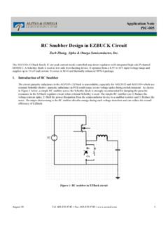
6 Simplified electrical distribution system for data can fail distribution equipment such as failures due to Circuit-Breaker-Induced switchingtransients are a major concern, which is receiving attention in adraft standard [1] and the focus of this Forensic Evidence for a Unique CaseConsider the case study of a new data center with a 26-kVdouble-ended loop-through feed to six dry-type transformerseach rated at 3000 kVA AA/3390 kVA FA and 26 kVand delta wye solidly grounded, as shown in Fig.
7 1. The trans-former primary winding is of 150-kV basic impulse insulationlevel (BIL). A vacuum breaker was used to switch the trans-former. The 4/0 cable between the breaker and the transformerwas 33 kV and 133% ethylene propylene rubber. Primaryarresters were installed. The transformers were fully tested,including turns ratio, insulation resistance, etc. Functional testswere completed, including uninterruptible power supply (UPS)full load, UPS transient , data center room validation, etc.
8 Inthe final phase of commissioning, a pull-the-plug test wasimplemented with the following )De-Energization Failure #1. Four electricians simultane-ously opened four 26-kV vacuum breakers to simulatea general utility outage. All systems successfully trans-ferred to standby generation but a loud pop was heardin Substation Room B and the relay for the vacuum circuitbreaker feeding Transformer TB3 signaled a )Energization Failure #2. Minutes later, two electri-cians simultaneously closed two 26-kV vacuum break-ers to substation Room A.
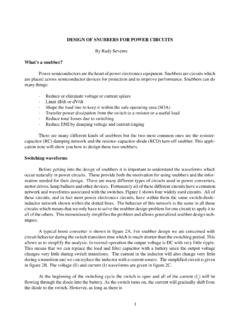
9 Transformer TA3 $ 2010 IEEE708 IEEE TRANSACTIONS ON INDUSTRY APPLICATIONS, VOL. 47, NO. 2, MARCH/APRIL 2011 Fig. 2. Transformer Failure #2 during 3. Transformer Failure #1 during #2 is shown in Fig. 2. Examination of the primarywindings revealed that the coil-to-coil tap burnt off and thewinding terminal showed an upward twist. The burn marksfrom the initial Flash indicated the transient concentrated onthe first turns of the windings. Typically, closing the vacuumbreaker to energize the Transformer is the worst #1 is shown in Fig.
10 3. Examination of the primarywindings revealed Flash and burn marks on the B-phase wind-ing at the bottom and middle. Those at the top indicate a coil-to-coil Failure , not a winding-to-winding Failure , and indicate atransient voltage with highdv/dt. Those in the middle were aresult of the cable (used to make the delta connection) swingingfree. Supports were only lacking for this jumper (oversightduring manufacturing) which could not withstand the forces ofthe transient . This Transformer passed the BIL test at 150-kVBIL but ultimately failed at 162-kV six transformers and cables were identical, but onlytwo failed during the vacuum- circuit - breaker switching .