Transcription of Transformer Protection Principles - GE Grid Solutions
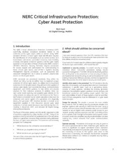
1 45 Transformer Protection Principles1. IntroductionTransformers are a critical and expensive component of the power system. Due to the long lead time for repair of and replacement of transformers , a major goal of Transformer Protection is limiting the damage to a faulted Transformer . Some Protection functions, such as overexcitation Protection and temperature-based Protection may aid this goal by identifying operating conditions that may cause Transformer failure. The comprehensive Transformer Protection provided by multiple function protective relays is appropriate for critical transformers of all Transformer Protection OverviewThe type of Protection for the transformers varies depending on the application and the importance of the Transformer .
2 transformers are protected primarily against faults and overloads. The type of Protection used should minimize the time of disconnection for faults within the Transformer and to reduce the risk of catastrophic failure to simplify eventual repair. Any extended operation of the Transformer under abnormal condition such as faults or overloads compromises the life of the Transformer , which means adequate Protection should be provided for quicker isolation of the Transformer under such Transformer FailuresFailures in transformers can be classified into winding failures due to short circuits (turn-turn faults, phase-phase faults, phase-ground, open winding) core faults (core insulation failure, shorted laminations) terminal failures (open leads, loose connections, short circuits)
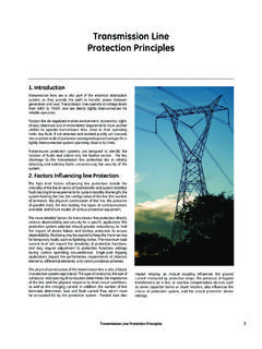
3 On-load tap changer failures (mechanical, electrical, short circuit , overheating) abnormal operating conditions (overfluxing, overloading, overvoltage) external faults4. Innovative GE Multilin Solutions to Transformer Protection Differential CharacteristicThe major operating challenge to Transformer differential Protection is maintaining security during CT saturation for external faults while maintaining sensitivity to detect low magnitude internal faults. CT saturation reduces the secondary output current from the CT, and causes a false differential current to appear to the relay.
4 GE Multilin differential relays meet this challenge in the following ways: the restraint current is based on the maximum measured winding current , as opposed to the traditional magnitude sum of the currents. This ensures ideal restraint for the actual fault condition, balancing sensitivity and security. the differential element uses a dual slope-dual breakpoint characteristic. The differential element can be set to account for both DC and AC saturation of the CTs, ensuring security, while maintaining sensitivity. Available in the T60, T35.
5 ConditionsProtection PhilosophyInternalWinding Phase-Phase, Phase-Ground faultsDifferential (87T), overcurrent (51, 51N)Restricted ground fault Protection (87 RGF)Winding inter-turn faultsDifferential (87T), Buchholz relay, Core insulation failure, shorted laminationsDifferential (87T), Buchholz relay, sudden pressure relayTank faultsDifferential (87T), Buchholz relay and tank-ground protectionOverfluxingVolts/Hz (24)ExternalOverloadsThermal (49)OvervoltageOvervoltage (59)OverfluxingVolts/Hz (24)External system short circuitsTime overcurrent (51, 51G), Instantaneous overcurrent (50, 50G) Transformer Protection Principles46 Transformer Protection Inrush Inhibit during Transformer Energization:The Transformer energization resembles the condition of an internal fault.
6 If no inhibiting mechanism is provided, the differential element will trip. The magnetizing inrush current has significant 2nd harmonic content . The level of 2nd harmonic current can be used to differentiate between inrush and a fault condition. The UR T60 and T35 GE Multilin Transformer relays use two different 2nd harmonic modes to inhibit the differential element for inrush. Traditional 2nd harmonic blocking The traditional 2nd harmonic restraint responds to the ratio of the magnitudes of the 2nd harmonic and the fundamental frequency currents. Adaptive 2nd harmonic blocking The adaptive 2nd harmonic blocking responds to both magnitudes and phase angles of the 2nd harmonic and the fundamental frequency currents.
7 The differential element correctly distinguishes between faults and Transformer energization, when the 2nd harmonic current is less than the entered 2nd harmonic setting. While levels of 2nd harmonic during inrush often do not go below 20%, many transformers are susceptible of generating lower 2nd harmonic current during energization. Setting the 2nd harmonic restraint below 20% may result in incorrect inhibit of the differential element during some internal fault events. The adaptive 2nd harmonic blocking allows settings in the traditional 20% range, while maintaining the security of the differential element against in the T60, alternative method for inrush inhibit is also available, where either current , voltage, or breaker status is used to indicate a de-energized Transformer .
8 The threshold can be lowered during energization of the Transformer as indicated either by breaker contact , current or voltage sensing, and will last for a settable time delay. This allows settings of less than 20% for inrush inhibit during Transformer in the Sensitive Ground Fault Protection to limit Transformer DamageDifferential and overcurrent Protection do not provide adequate Protection for wye-connected windings with grounded neutrals. Faults close to the neutral produces lesser fault current as shown by the current distribution curve. The restricted ground fault function can be used to provide differential Protection for such ground faults, down to faults at 5% of the Transformer winding.
9 Restricted ground fault Protection can be a low impedance differential function or a high impedance differential function. The low impedance function has the advantage to being able to precisely set the sensitivity to meet the application requirement . This sensitive Protection limits the damage to the Transformer to allow quicker repair. The restricted ground fault element uses adaptive restraint based on symmetrical components to provide security during external phase faults with significant CT error. This permits the function to maximize sensitivity without any time in the 745, Overflux Protection Transformer overfluxing can be a result of Overvoltage Low system frequencyA Transformer is designed to operate at or below a maximum magnetic flux density in the Transformer core.
10 Above this design limit the eddy currents in the core and nearby conductive components cause overheating which within a very short time may cause severe damage. The magnetic flux in the core is proportional to the voltage applied to the winding divided by the impedance of the winding. The flux in the core increases with either increasing voltage or decreasing frequency. During startup or shutdown of generator-connected transformers , or following a load rejection, the Transformer may experience an excessive ratio of volts to hertz, that is, become overexcited. When a Transformer core is overexcited, the core is operating in a non-linear magnetic region, and creates harmonic components in the exciting current.