Example: biology
Transom-Mount Transducer Installation Instructions
2. Pull the cable back and slide the transducer into the mounting bracket . 3. Place a 5 mm flat washer on the 10-32 x 1.75 in. screw and insert the screw through the mounting bracket, transducer, spacer, and rubber washer. 4. Place a 5 mm flat washer on the exposed end of the 10-32 x 1.75 in. screw, and fasten it with the 10-32 lock nut .
Tags:
Information
Domain:
Source:
Link to this page:
Documents from same domain
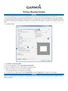
Printing a Mounting Template - Garmin
static.garmin.comPrinting a Mounting Template Notice It is not recommended that you print a mounting template on your own. Use the template that came in the product box.
Instructions - Garmin
static.garmin.com1 GLO™ GLONASS and GPS Sensor Instructions August 2012 190-01492-00_0B Printed in Taiwan
EDGE® 1030 Owner’s Manual - Garmin International
static.garmin.comCharging the Device NOTICE To prevent corrosion, thoroughly dry the USB port, the weather cap, and the surrounding area before charging or connecting to
Owner’s Manual - Garmin International
static.garmin.comIntroduction WARNING See the Important Safety and Product Information guide in the product box for product warnings and other important information.
Lidar Lite v3 Operation Manual 2 and Technical …
static.garmin.com1 Lidar Lite v3 Operation Manual and Technical Specifications Laser Safety WARNING This device requires no regular maintenance. In the event that the device

GPSMAP 62 series - Garmin
static.garmin.comGPSMAP 62 Series Quick Start Manual 3 3. Replace the battery cover. For best results, after you install new batteries, update the battery type in the

Important Safety and Product Information 2 …
static.garmin.comIMPORTANT SAFETY AND PRODUCT INFORMATION WARNING Failure to heed the following warnings could result in an accident or collision resulting in death or
Important Safety and Product Information 2 …
static.garmin.comImportant Safety and Product Information 2 Informations importantes sur le produit et la sécurité 3 guida Informazioni importanti sulla sicurezza e sul

GNS 430(A) - Garmin International
static.garmin.com190-00140-00 Rev. P GNS 430(A) Pilot’s Guide and Reference i RECORD OF REVISIONS Revision Date of Revision Description A 12/98 Initial Release B 4/99 Update to conform to recent SW changes

GNS 530(A) - Garmin International
static.garmin.com190-00181-00 Rev. H GNS 530(A) Pilot’s Guide and Reference i RECORD OF REVISIONS Revision Date of Revision Description A 5/00 Initial Release B 5/01 Update to reflect software changes through 2.06
Related documents

Library Ladder Assembly Instructions
go.rockler.comAssembly Instructions Congratulations on your purchase of the Library Ladder Hardware Kit! These instructions will guide you through the process of building a 7-step (8 foot) ladder. Familiarity with the instructions will make the process ... Drill a 7/16" hole for mounting the Aluminum Decorative Spindle (5). 3.
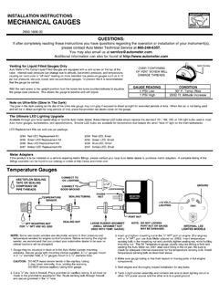
INSTALLATION INSTRUCTIONS MECHANICAL GAUGES
autometer.companels. Secure gauge with the mounting bracket provided. NOTE:If alternate gauge mounting is used other than in-dash or under dash, mounting provisions may have to be determined by the installer. 5. Make sure the nitrous bottle valve is closed. 6. Secure an in-line gauge adapter (eg. NOS part #16770 or #16771) in a vice.

Installation Instructions Features and Specifications for ...
assets.bluesea.comInstallation Instructions Mounting • To avoid corrosion to connecting wires and terminals, mount in a dry and protected location if possible. Avoid locations directly above the battery banks. Electrical Connections • The wiring diagrams illustrated on the back page represent common installations and are not meant to
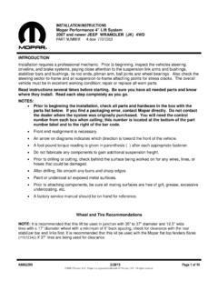
INSTALLATION INSTRUCTIONS Mopar Performance 4” Lift …
starparts.chrysler.comINSTALLATION INSTRUCTIONS Mopar Performance 4” Lift System 2007 and newer JEEP WRANGLER (JK) 4WD PART NUMBER 4-door 77072353 K6862295 2/28/15 Page 2 of 16 ... Install the mounting bolt (2) for the brake hose to the frame routing clip and tighten to 20 N·m (177 in. lbs.).

Installation Instructions: Hinge Kit
go.rockler.comfinished product during the process of mounting the hinges and adjusting the unit. Installation Instructions: Hinge Kit The Invisidoor hinge kit is designed to offer a durable hinge system for a hidden door with the easiest installation on the market. The hinge was engineered to offer versatility for the Invisidoor universal bookcase which

L4064B Universal Combination Fan and Limit Controllers
customer.honeywell.commanufacturer Õs instructions. The element must not touch any internal part of the furnace. The electrical rating is at maximum switch temperature of 190 OF (88 C). If plenum surface temperature exceeds 190 O F (88 O C), heat insulating material or a mounting bracket must be u s e d . MOUNTING The device may be mounted either on the

INSTALLATION INSTRUCTIONS - manuals.frigidaire.com
manuals.frigidaire.com1 installation instructions - freestanding gas range installation and service must be performed by a qualified installer. important: save for local electrical inspector’s use.
LAKEWOOD/QUICKTIME SAFETY BELLHOUSING
documents.holley.cominto the bellhousing before mounting it to the engine. PREPARATION FOR INSTALLATION 1. Place vehicle on a solid, level surface such as a garage floor to ensure safe installation. 2. Raise vehicle using appropriate lifting device and support it using automotive approved support stands having adequate load …

HYPERSPARK EFI IGNITION BOX 556-151
documents.holley.comMOUNTING: The HyperSpark EFI Ignition can be mounted in most positions, except directly upside down (if upside down, moisture or water cannot escape). It can be mounted in the engine compartment as long as it is away from direct engine heat sources. It is not recommended to mount the unit in an enclosed area, such as the glove box.

Operator’s Manual: Trijicon Ruggedized Miniature Reflex (RMR)
images-na.ssl-images-amazon.comMounting to Firearm Adapters are available to attach the RMR sights to various firearms. See page 30 for adapter options. 15 ADJUSTMENT PROCEDURES CAUTION The windage and elevation adjusters should never be moved all the way to the extremes in adjustment. It is possible that over-adjustment