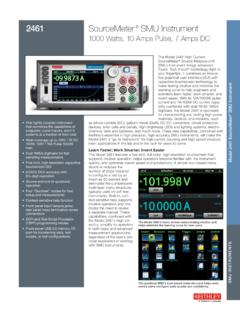
Transcription of TRANSZORB Transient Voltage Suppressors - Vishay
1 Thru General Semiconductor Revision: 03-Mar-20201 Document Number: 88369 For technical questions within your region: DOCUMENT IS SUBJECT TO CHANGE WITHOUT NOTICE. THE PRODUCTS DESCRIBED HEREIN AND THIS DOCUMENTARE SUBJECT TO SPECIFIC DISCLAIMERS, SET FORTH AT Transient Voltage SuppressorsDEVICES FOR BI-DIRECTION APPLICATIONSFor bi-directional types, use CA suffix ( P6KE440CA). Electrical characteristics apply in both Glass passivated chip junction Available in uni-directional and bi-directional 600 W peak pulse power capability with a 10/1000 s waveform, repetitive rate (duty cycle): % Excellent clamping capability Very fast response time Low incremental surge resistance Solder dip 275 C max.
2 10 s, per JESD 22-B106 AEC-Q101 qualified Material categorization: for definitions of compliance please see APPLICATIONSUse in sensitive electronics protection against Voltage transients induced by inductive load switching and lighting on ICs, MOSFET, signal lines of sensor units for consumer, computer, industrial, automotive, and DATACase: DO-15 (DO-204AC) Molded epoxy over passivated chip Molding compound meets UL 94 V-0 flammability rating Base P/N-E3 - RoHS compliant, commercial grade Base P/NHE3 - RoHS compliant, AEC-Q101 qualifiedTerminals: matte tin plated leads, solderable per J-STD-002 and JESD 22-B102 E3 suffix meets JESD 201 class 1A whisker test, HE3 suffix meets JESD 201 class 2 whisker testNote P6KE250A to P6KE540A and P6KE250CA to P6KE440CA for commercial grade onlyPolarity.
3 For uni-directional types the color band denotes cathode end, no marking on bi-directional typesNotes(1)Non-repetitive current pulse, per fig. 3 and derated above TA = 25 C per fig. 2(2)Measured on ms single half sine-wave or equivalent square wave, duty cycle = 4 pulses per minute maximum(3)VF = V for P6KE220A and below; VF = V for P6KE250A and abovePRIMARY V to 459 VVBR V to 540 VVBR V to 440 VPPPM600 WIFSM (uni-directional only)100 ATJ CPolarityUni-directional, bi-directionalPackageDO-15 (DO-204AC)DO-15 (DO-204AC)MAXIMUM RATINGS (TA = 25 C unless otherwise noted)PARAMETERSYMBOLVALUEUNITPeak pulse power dissipation with a 10/1000 s waveform (1) (fig.)
4 1)PPPM600 WPeak pulse current with a 10/1000 s waveform (1) IPPMSee next tableAPower dissipation on infinite heatsink at TL = 75 C (fig. 5) forward surge current ms single half sine-wave (2)IFSM100 AMaximum instantaneous forward Voltage at 50 A for uni-directional only (3) junction and storage temperature rangeTJ, TSTG- 55 to + 175 thru General Semiconductor Revision: 03-Mar-20202 Document Number: 88369 For technical questions within your region: DOCUMENT IS SUBJECT TO CHANGE WITHOUT NOTICE. THE PRODUCTS DESCRIBED HEREIN AND THIS DOCUMENTARE SUBJECT TO SPECIFIC DISCLAIMERS, SET FORTH AT (1) Pulse test: tp 50 ms(2) Surge current waveform per fig.
5 3 and derate per fig. 2(3) For bi-directional types with VWM of 10 V and less the ID limit is doubled(4) All terms and symbols are consistent with ANSI/EEE (+) Underwriters laboratory recognition for the classification of protectors (QVGQ2) under the UL standard for safety 497B and file number E136766 for both uni-directional and bi-directional devicesELECTRICAL CHARACTERISTICS (TA = 25 C unless otherwise noted)DEVICE TYPEBREAKDOWN Voltage VBR AT IT (1)(V) TEST CURRENT IT(mA)STAND-OFF VOLTAGEVWM (V)MAXIMUMREVERSELEAKAGE AT VWM (3) ID ( A)
6 MAXIMUMPEAK PULSE CURRENT IPPM (2) (A) MAXIMUMCLAMPINGVOLTAGE AT IPPMVC (V) MAXIMUM TEMPERATURE COEFFICIENT AT VBR(%/ C) (+) (+) (+) (+) (+) (+) (+) (+) (+) (+) (+) (+) (+) (+) (+) (+) (+) (+) (+) (+) (+) (+) (+) (+) (+) (+) (+) (+) (+) (+) (+) (+) (+) (+) (+) (+) (+) (+) (+) (+) (+) (+) (+) thru General Semiconductor Revision: 03-Mar-20203 Document Number: 88369 For technical questions within your region: DOCUMENT IS SUBJECT TO CHANGE WITHOUT NOTICE. THE PRODUCTS DESCRIBED HEREIN AND THIS DOCUMENTARE SUBJECT TO SPECIFIC DISCLAIMERS, SET FORTH AT (1) AEC-Q101 qualifiedRATINGS AND CHARACTERISTICS CURVES (TA = 25 C unless otherwise noted)Fig.
7 1 - Peak Pulse Power Rating CurveFig. 2 - Pulse Power or Current vs. Initial Junction TemperatureFig. 3 - Pulse WaveformFig. 4 - Typical Junction Capacitance Uni-DirectionalTHERMAL CHARACTERISTICS (TA = 25 C unless otherwise noted)PARAMETERSYMBOLVALUEUNITT ypical thermal resistance, junction to leadR JL20 C/ WTypical thermal resistance, junction to ambientR JA75 ORDERING INFORMATION (Example)PREFERRED PINUNIT WEIGHT (g)PREFERRED PACKAGE CODEBASE QUANTITYDELIVERY " diameter paper tape and (1) " diameter paper tape and reeltd - Pulse Width (s) ms10 s10 s100 sNon-Repetitive PulseWaveform shown in Fig.
8 3TA = 25 CPPPM - Peak Pulse Power (kW)10075502500255075100125150175200 Peak Pulse Power (PPP) or Current (IPP)Derating in Percentage, %TJ - Initial Temperature ( C) - Peak Pulse Current, % IRSMt - Time (ms)tr = 10 sPeak ValueIPPMHalf Value -IPPMIPP210/1000 s Waveformas defined by = 25 CPulse Width (td)is defined as the Pointwhere the Peak Currentdecays to 50 % of - Junction Capacitance (pF)VBR - Breakdown Voltage (V)TJ = 25 Cf = MHzVsig = 50 mVp-pMeasured atZero BiasMeasured at Stand-OffVoltage thru General Semiconductor Revision: 03-Mar-20204 Document Number: 88369 For technical questions within your region: DOCUMENT IS SUBJECT TO CHANGE WITHOUT NOTICE.
9 THE PRODUCTS DESCRIBED HEREIN AND THIS DOCUMENTARE SUBJECT TO SPECIFIC DISCLAIMERS, SET FORTH AT 5 - Power Derating CurveFig. 6 - Maximum Non-Repetitive Forward Surge CurrentFig. 7 - Typical Transient Thermal Impedance65432100255075100125150175200L = " ( mm)Lead LengthsPD - Power Dissipation (W)TL - Lead Temperature ( C)60 HzResistive orInductive Load20010050 101 51050100 IFSM - Peak Forward Surge Current (A)Number of Cycles at 60 Hz Uni-Directional OnlyTJ = TJ ms Single Half Sine-Wavetp - Pulse Duration (s) Transient Thermal Impedance ( C/W) thru General Semiconductor Revision: 03-Mar-20205 Document Number: 88369 For technical questions within your region.
10 DOCUMENT IS SUBJECT TO CHANGE WITHOUT NOTICE. THE PRODUCTS DESCRIBED HEREIN AND THIS DOCUMENTARE SUBJECT TO SPECIFIC DISCLAIMERS, SET FORTH AT OUTLINE DIMENSIONS in inches (millimeters)Note Dimensions of mold length and diameter do not include mold flash and gate burr, mold flash shall not exceed inch per side. These dimensions are measured at the outermost extreme of the plastic body APPLICATION NOTES This P6KE TVS series is a low cost commercial product for use in applications where large Voltage transients can permanently damage Voltage -sensitive components.