Transcription of Troubleshooting Manual - About Us | JustAnswer
1 TS2470EN. Troubleshooting Manual allison Transmission MD/HD/ b series transmissions WTEC II Controls (Pre-TransID and TID 1). MD 3060/MD 3066/MD 3560(P)(R). MD 3070PT. HD 4060/HD 4560(P)(R). B 300/B 400/ B 500(P)(R). May 1998. Revision 1, 199910. Division of General Motors Corporation Box 894 Indianapolis, Indiana 46206-0894. Printed in the Copyright 1998 General Motors Corp. W T E C I I E L E C T RO N I C C O N T RO L S T RO U B L E S H O OT I N G M A N UA L. FOREWORD How to Use This Manual This Manual provides Troubleshooting information for allison Transmission Division, MD/HD/ b series transmissions . Service Manuals SM2148EN and SM2457EN, and Parts Catalogs PC2150EN and PC2456EN may be used in conjunction with this Manual . This Manual includes: Description of the WTEC II electronic control system. Description of the electronic control system components. Description of diagnostic codes, system responses to faults, and Troubleshooting . Wire, terminal, and connector repair information.
2 Specific instructions for using many of the available or required service tools and equipment are not included in this Manual . The service tool manufacturer will furnish instructions for using the tools or equipment. Additional information may be published from time to time in Service Information Letters (SIL) and will be included in future revisions of this and other manuals. Please use these SILs to obtain up-to-date information concerning allison Transmission products. This publication is revised periodically to include improvements, new models, special tools, and procedures. A. revision is indicated by a letter suffix added to the publication number. Check with your allison Transmission service outlet for the currently applicable publication. Additional copies of this publication may be purchased from authorized allison Transmission service outlets. Look in your telephone directory under the heading of transmissions Truck, Tractor, etc. Take time to review the Table of Contents and the Manual .
3 Reviewing the Table of Contents will aid you in quickly locating information. NOTE: allison Transmission is providing for service of WTEC II wiring harnesses and wiring harness components as follows: (See Service Information Letter 1-WT-97 for further information.). Repair parts for the internal wiring harness and for wiring harness components attached to the shift selector will be available through the allison Transmission Parts Distribution Center (PDC). Use the P/N from your appropriate parts catalog or from Appendix E in this Manual . allison Transmission is responsible for warranty on these parts. Since January, 1998, all WTEC II external harnesses and external harness components must be obtained from St. Clair Technologies Inc. (SCTI). SCTI provides parts to any allison customer or OEM and is responsible for warranty on these parts. SCTI recognizes ATD, manufacturers, and SCTI part numbers. SCTI provides a technical HELPLINE at 519-627-1673 (Wallaceburg).
4 SCTI has parts catalogs available. The SCTI addresses and phone numbers for parts outlets are: St. Clair Technologies, Inc. St. Clair Technologies, Inc. St. Clair Technologies, Inc. 1050 Old Glass Road 1111 Mikesell Street c/o Mequilas Tetakawi Wallaceburg, Ontario, Canada, N8A 3T2 Charlotte, Michigan 48813 Carr. Internationale KM 1969. Phone: (519) 627-1673 Phone: (517) 541-8166 Guadalajara Nogales, KM2. Fax: (519) 627-4227 Fax: (517) 541-8167 Empalme, Sonora, Mexico Phone: 011-52-622-34661. Fax: 011-52-622-34662. ii Copyright 1998 General Motors Corp. W T E C I I I E L E C T RO N I C C O N T RO L S T RO U B L E S H O OT I N G M A N UA L. IMPORTANT SAFETY NOTICE. IT IS YOUR RESPONSIBILITY to be completely familiar with the warnings and cautions used in this Manual . These warnings and cautions advise against using specific service procedures that can result in personal injury, equipment damage, or cause the equipment to become unsafe. These warnings and cautions are not exhaustive.
5 allison Transmission could not possibly know, evaluate, or advise the service trade of all conceivable procedures by which service might be performed or of the possible hazardous consequences of each procedure. Consequently, allison Transmission has not undertaken any such broad evaluation. Accordingly, ANYONE WHO USES A SERVICE PROCEDURE OR TOOL WHICH IS NOT. RECOMMENDED BY allison TRANSMISSION MUST first be thoroughly satisfied that neither personal safety nor equipment safety will be jeopardized by the service proce- dures used. Also, be sure to review and observe WARNINGS, CAUTIONS, and NOTES provided by the vehicle manufacturer and/or body builder before servicing the allison transmission in that vehicle. Proper service and repair is important to the safe and reliable operation of the equipment. The service procedures recommended by allison Transmission and described in this Manual are effective methods for performing Troubleshooting operations.
6 Some procedures require using specially designed tools. Use special tools when and in the manner recommended. The WARNINGS, CAUTIONS, and NOTES in this Manual apply only to the allison transmission and not to other vehicle systems which may interact with the transmission. Be sure to review and observe any vehicle system information provided by the vehicle manufacturer and/or body builder at all times the allison transmission is being serviced. WARNINGS, CAUTIONS, AND NOTES. Three types of headings are used in this Manual to attract your attention: Is used when an operating procedure, practice, etc., which, if not correctly followed, WARNING! could result in injury or loss of life. Is used when an operating procedure, practice, etc., which, if not strictly observed, could CAUTION: result in damage to or destruction of equipment. NOTE: Is used when an operating procedure, practice, etc., is essential to highlight. Copyright 1998 General Motors Corp. iii W T E C I I E L E C T RO N I C C O N T RO L S T RO U B L E S H O OT I N G M A N UA L.
7 TRADEMARKS USED IN THIS Manual . The following trademarks are the property of the companies indicated: LPS Cleaner is a registered trademark of LPS Laboratories. VCI #10 is the registered trademark for a vapor phase rust preventive manufactured by Daubert Chemical Company, Chicago, Illinois. VCI #10 is covered by Military Specifications MIL-L-46002 (ORD) and MIL-I-23310 (WEP) under the designation of Nucle Oil. Biobor JF is the registered trademark for a biological inhibitor manufactured by Hammonds Fuel Additives Corporation. Loctite is a registered trademark of the Loctite Corporation. Teflon is a registered trademark of the DuPont Corporation. Pro-Link is a registered trademark of MicroProcessor Systems, Inc. SHIFT SELECTOR TERMS AND DISPLAY INDICATIONS. Shift selector terms and displays are represented in this Manual as follows: Button Names , DISPLAY MODE, MONITOR, SELECT, etc. Transmission Ranges D (Drive), N (Neutral), 1 (First), R (Reverse), etc.
8 Displays OL , OK , etc. iv Copyright 1998 General Motors Corp. WTEC I I EII. WTEC L EELECTRONIC. C T RO N I C CCONTROLS. O N T RO L S Troubleshooting . T RO U B L E S H O OT I NMANUAL. G M A N UA L. TABLE OF CONTENTS. Page Foreword..i SAFETY INFORMATION. Important Safety Notice .. iii Warnings, Cautions, and Notes .. iii Trademarks Used in This Manual .. iv Shift Selector Terms and Display Indications.. iv SECTION 1. GENERAL DESCRIPTION. 1 1. TRANSMISSION .. 1 1. 1 2. ELECTRONIC CONTROL UNIT (ECU) .. 1 3. 1 3. SHIFT SELECTOR .. 1 3. A. Pushbutton Shift Selector .. 1 3. B. Lever Shift Selector .. 1 4. 1 4. THROTTLE POSITION SENSOR.. 1 4. 1 5. SPEED SENSORS .. 1 5. 1 6. CONTROL MODULE .. 1 6. 1 7. WIRING HARNESSES .. 1 7. A. External Wiring Harness.. 1 7. B. Internal Wiring Harness .. 1 8. 1 8. VEHICLE INTERFACE MODULE.. 1 10. 1-9. TRANSID FEATURE .. 1-10. SECTION 2. DEFINITIONS AND ABBREVIATIONS. 2 1. DO NOT SHIFT LIGHT.. 2 1. 2 2. DIAGNOSTIC DATA READER.
9 2 1. 2 3. ABBREVIATIONS.. 2 2. SECTION 3. BASIC KNOWLEDGE. 3 1. BASIC KNOWLEDGE REQUIRED .. 3 1. 3 2. USING THE Troubleshooting Manual .. 3 1. 3 3. SYSTEM OVERVIEW .. 3 2. 3 4. IMPORTANT INFORMATION IN THE Troubleshooting PROCESS .. 3 2. 3 5. BEGINNING THE Troubleshooting PROCESS .. 3 3. SECTION 4. WIRE CHECK PROCEDURES. 4 1. CHECKING OPENS, SHORTS BETWEEN WIRES, AND SHORTS-TO-GROUND .. 4 1. 4 2. CHECKING AT TRANSMISSION CONNECTOR AND THE INTERNAL HARNESS. FOR OPENS, SHORTS BETWEEN WIRES, AND SHORTS-TO-GROUND .. 4 2. Copyright 1998 General Motors Corp. v WTEC I I EII. WTEC L EELECTRONIC. C T RO N I C CCONTROLS. O N T RO L S Troubleshooting . T RO U B L E S H O OT I NMANUAL. G M A N UA L. T A B L E O F C O N T E N T S (C o n t ' d). SECTION 5. OIL LEVEL SENSOR Page 5 1. ELECTRONIC FLUID LEVEL CHECK (SHIFT SELECTOR) .. 5 1. A. Fluid Level Check Procedure .. 5 1. 5 2. ELECTRONIC FLUID LEVEL CHECK (PRO-LINK 9000) .. 5 4. A. Fluid Level Check Procedure.
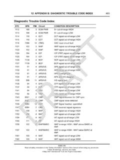
10 5 4. SECTION 6. DIAGNOSTIC CODES. 6 1. DIAGNOSTIC CODE MEMORY .. 6 1. 6 2. CODE READING AND CODE CLEARING .. 6 1. 6 3. DIAGNOSTIC CODE RESPONSE .. 6 3. 6 4. SHIFT SELECTOR DISPLAYS RELATED TO ACTIVE CODES .. 6 3. 6 5. DIAGNOSTIC CODE LIST AND DESCRIPTION.. 6 4. 6 6. DIAGNOSTIC CODE Troubleshooting .. 6 17. A. Beginning the Troubleshooting Process .. 6 17. B. Solenoid Locations .. 6 17. C. Diagnostic Code Schematics .. 6 18. D. Diagnostic Code 13 and 35 Schematics .. 6 18. SECTION 7. INPUT AND OUTPUT FUNCTIONS. 7 1. INPUT FUNCTIONS .. 7 1. 7 2. OUTPUT FUNCTIONS .. 7 3. SECTION 8. GENERAL Troubleshooting OF PERFORMANCE COMPLAINTS. 8 1. GENERAL NOTES .. 8 1. 8 2. Troubleshooting PERFORMANCE COMPLAINTS .. 8 2. APPENDICES. A. IDENTIFICATION OF POTENTIAL CIRCUIT PROBLEMS .. A 1. B. CHECKING CLUTCH PRESSURES .. B 1. C. SOLENOID AND CLUTCH CHART .. C 1. D. WIRE/CONNECTOR CHART.. D 1. E. CONNECTOR PART NUMBERS, TERMINAL PART NUMBERS, TOOL PART NUMBERS, AND REPAIR INSTRUCTIONS.