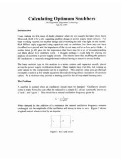
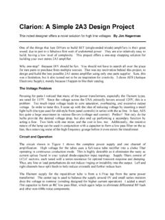
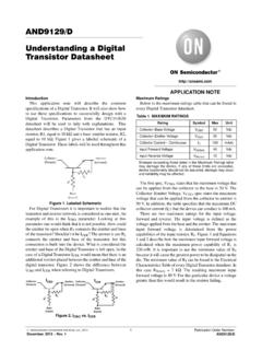
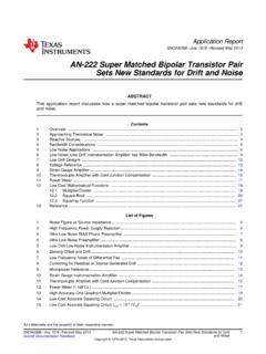
Transcription of Two transistor circuit replaces IC - hagtech.com
1 Two transistor circuit replaces IC Jim Hagerman, Hagerman Technology LLC, Honolulu, HI, I am always impressed with the way semiconductor manufacturers go out of their way to make the end designer s job easier. One example is the LTC4300 recently introduced by Linear Technology. This chip buffers I2C clock and data lines to/from a hot-swappable card. No easy task since it must work bi-directionally (both sides can be driven actively at the same time) without latching. However, as is sometimes the case, a complicated circuit can be replaced by a simple one without much loss of performance. The entire IC can be replaced by four transistors and two resistors. Schematic 1 shows the circuit for one signal only (either clock or data).
2 Two NPN transistors wired head-to-tail form the heart of the circuit . I2C signals are open collector (or drain) type so can only actively pull down. When ENABLE is high, a low going SCL signal drives the emitter of one of the transistors as a common base amplifier. The 10k resistor in the base provides enough current to saturate the collector and drop the Vce voltage to about , thereby pulling the other side low. It is like a very efficient diode. With ENABLE low, the hot swappable side has no affect on the signal, with or without power. Schematic 1. circuit of I2C hot-swappable level translator/buffer (clock side shown). The two- transistor circuit offers the additional benefit of acting as a level translator between two different logic levels.
3 In this example, I show a buffer/translation between a system and a 5V card. For proper operation, the ENABLE line must not go higher than the lower of the two VCC. The photos show actual operation at 100kHz. There are some edge glitches and overshoot on the signal (due to transistor junction capacitance), but should be acceptable for many low-cost applications. Photo 1. circuit driven by 5V side. Photo 2. circuit driven by side. [1] Two transistors form bi-directional level translator , Jim Hagerman, EDN 11/7/96 [2] Low-voltage interface circuits translate to 5V , CC Poon & Edward Cui, EDN 11/5/98