Transcription of AND9129/D Understanding a Digital Transistor …
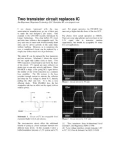
1 Semiconductor Components Industries, LLC, 2013 December, 2013 Rev. 11 Publication Order Number:AND9129/DAND9129/DUnderstanding a DigitalTransistor DatasheetIntroductionThis application note will describe the commonspecifications of a Digital Transistor . It will also show howto use these specifications to successfully design with aDigital Transistor . Parameters from the DTC114E/Ddatasheet will be used to help with explanations. Thisdatasheet describes a Digital Transistor that has an inputresistor, R1, equal to 10 kW and a base emitter resistor, R2,equal to 10 kW. Figure 1 gives a labeled schematic of aDigital Transistor . These labels will be used throughout thisapplication 1. Labeled SchematicFor Digital Transistors it is important to realize that thetransistor and resistor network is considered as one unit.
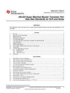
2 Anexample of this is the ICBO parameter. Looking at thisparameter one would think that it is not possible. How couldthe emitter be open when R2 connects the emitter and baseof the Transistor ? Shouldn t it be ICER? The answer is yes R2connects the emitter and base of the Transistor , but thisconnection is built into the device. What is considered theemitter and base of the Digital Transistor is left open. In thecase of a Digital Transistor ICER would mean that there is anadditional resistor placed between the emitter and base of thedigital Transistor . Figure 2 shows the difference betweenICBO and ICER when referring to Digital 2. ICBO vs. ICERM aximum RatingsBelow is the maximum ratings table that can be found inevery Digital Transistor 1. MAXIMUM RATINGSR atingSymbolMaxUnitCollector Base VoltageVCBO50 VdcCollector Emitter VoltageVCEO50 VdcCollector Current ContinuousIC100mAdcInput Forward VoltageVIN(fwd)40 VdcInput Reverse VoltageVIN(rev)10 VdcStresses exceeding those listed in the Maximum Ratings tablemay damage the device.
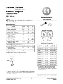
3 If any of these limits are exceeded,device functionality should not be assumed, damage may occurand reliability may be first spec, VCBO, states that the maximum voltage thatcan be applied from the collector to the base is 50 V. TheCollector Emitter Voltage, VCEO, spec states the maximumvoltage that can be applied from the collector to emitter is50 V. In addition, the table specifies that the maximum DCcollector current (IC) that the device can conduct is 100 are two maximum ratings for the input voltage,forward and reverse. The input voltage is defined as thevoltage applied from the base and the emitter. The maximuminput forward voltage is determined from the powercapabilities of the input resistor, R1. Figure 3 and Equations1 and 2 describe how the maximum input forward voltage iscalculated when the maximum power capability of R1 is220 mW.
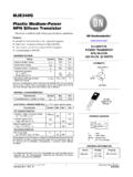
4 It is important to use the minimum value of R1because it will cause the greatest power to be dissipated on thedie. The minimum value of R1 can be found in the ElectricalCharacteristics Table of every Digital Transistor datasheet. Inthis case R1(min) = 7 kW. The resulting maximum inputforward voltage is 40 V. For this particular device a voltagegreater than this would result in the resistor 3. Input Forward Voltage+ 7000 + V(eq. 1)PR1+ VR1 2R1 VR1+PR1 R1 VIN(max)+VR1)VBE+ ) +40 V(eq. 2)The maximum input reverse voltage is determined by thebreakdown voltage of the base emitter junction and theresistor network. The equivalent circuit in Figure 4 can bedrawn when analyzing the maximum input reverse voltageand is justified by Equation 3. Looking at Figure 4 one seesthat it is just a simple voltage divider. The voltage dividerequation is shown in Equation 4.
5 In applications where alarge reverse voltage will be applied to the base emitterjunction it is recommended to use a Digital Transistor witha small R2 and large R1. This will cause the majority of thevoltage to be dropped across R1, thus a smaller voltage willbe dropped across R2 and consequently the base emitterjunction. The worst case for this spec is when R1 is at itsminimum value and R2 is at its maximum 4. Input Reverse Voltage Equivalent Circuit(eq. 3)When RBE R2,1 RBE)1R2+1R2 REquivalent+RBE R2+ 1 RBE)1R2 *1(eq. 4)REquivalent+ 1R2 *1+R2VB+VE R1R1)R2 Electrical CharacteristicsThe first section of the Electrical Characteristics Table hasspecs pertaining to when the Digital Transistor is OFF. Thereare three leakage current parameters ICBO, ICEO, and ICBO and ICEO, one can expect the leakage current to bebelow the value that is stated on the datasheet when a reversevoltage is applied between the respective , IEBO is dependent on both the input resistor andthe base emitter resistor.
6 The resistor network path issignificantly less resistive then the path through the reversedbiased base emitter junction. Ohm s Law is used todetermine the IEBO value. An example for a DigitalTransistor with R1(min) = 7 kW, R2(min) = 7 kW, and a VEB =6 V is shown below. It is important to note that the minimumvalue of 7 kW was used instead of 10 kW. This is donebecause it will estimate the largest possible leakage.(eq. 5)IEBO+6V7kW)7kW+ mADigital Transistors only specify the collector base,V(BR)CBO, and collector emitter, V(BR)CEO, breakdownvoltages. These ensure that the device will have abreakdown voltage above the specified second section of the Electrical Characteristics Tabledescribes specs for when the Digital Transistor is ON. Table2 will be used as an example to help explain the followingparameters.
7 First, the DC Current Gain, hFE, is aspecification of how much the base current will be amplifiedin resulting collector current. The hFE spec states that withan IC = mA and a VCE = 10 V one can expect the gain tobe around 60, but is ensured that it will be above 35. Thismeans that the base current, IB, will need to be 83 mA if thetypical gain of 60 is used.(eq. 6)IB+IChFE+5mA60+83mAThe next parameter is the Collector Emitter SaturationVoltage, VCE(sat). This parameter tells the designer themaximum voltage drop that will occur when the device isON. In this instance a maximum of 250 mV will be droppedacross the Transistor when the IC = 10 mA and the base isdriven with mA (hFE = 33). The hFE spec can be seen asa threshold current ratio of base drive to collector current. Ifthe base current is greater than the collector current dividedby the hFE spec then the Transistor begins to saturate and thecollector emitter voltage drops to the saturation most cases a Digital Transistor will be used as a are four parameters that characterize this operation:Input Voltage (off), Input Voltage (on), Output Voltage (on),and Output Voltage (off).
8 The first parameter, Input Voltage(off), states that an input voltage less than V will turn thedevice OFF (VCE = 5 V, IC = 100 mA). The Input Voltage (on)parameter defines that at a VCE = V and IC = 10 mA aminimum input voltage of V needs to be applied to turnthe device ON. These two parameters also list typical typical values are the measured voltages when thedevice is exactly at those ON and OFF conditions. It is notrecommended to operate the device at these voltages if onewants to ensure the device is ON/OFF. Figure 5 gives agraphical representation of these < V, device is OFFVi < V, device is typically OFFVi > V, device is typically ONVi > V, device is ONFigure 5. Output Voltage vs. Input VoltageThe output voltage of a switch is also very valuable to adesigner. The Output Voltage (on), VOL, spec states that theoutput voltage will be less than V under the followingconditions: VCC = V, VB = V, RL = kW.
9 The VOLis similar to the VCE(sat) of the device in that they bothdescribe the maximum voltage that will be dropped acrossthe collector emitter when the Digital Transistor is insaturation(ON). The conditions for the Output Voltage (off),VOH, spec are: VCC = V, VB = V, RL = kW. Underthese conditions the output voltage will be greater V. Refer to Figure 6 for further Understanding of the VOLand VOH 6. Output Voltage Test SchematicTable 2. ELECTRICAL CHARACTERISTICSC haracteristicsSymbolMinTypMaxUnitOFF CHARACTERISTICSC ollector Base Cutoff Current (VCB = 50 V, IE = 0)ICBO 100nAdcCollector Emitter Cutoff Current (VCE = 50 V, IB = 0)ICEO 500nAdcEmitter Base Cutoff Current (VEB = 6 V, IC = 0)IEBO Base Breakdown Voltage (IC = 10 mA, IE = 0)V(BR)CBO50 VdcCollector Emitter Breakdown Voltage (IC = mA, IB = 0)V(BR)CEO50 VdcON CHARACTERISTICSDC Current Gain (IC = mA, VCE = 10 V)hFE3560 Collector Emitter Saturation Voltage (IC = 10 mA, IB = mA)VCE(sat) Voltage (off) (VCE = V, IC = 100 mA)Vi(off) Voltage (on) (VCE = V, IC = 10 mA)Vi(on) VdcOutput Voltage (on) (VCC = V, VB = V, RL = kW)VOL Voltage (off) (VCC = V, VB = V, RL = kW)
10 VdcInput RatioR1 parametric performance is indicated in the Electrical Characteristics for the listed test conditions, unless otherwise noted. Productperformance may not be indicated by the Electrical Characteristics if operated under different are two curves present on all Digital Transistordatasheet that provide more data on the Vi(on) and Vi(off)parameters. The first is the Output Current vs. Input Voltage,Figure 7. This curve characterizes the Vi(off) parameter, andthe data was taken when the VCE or the output voltage is 5 can use this curve to determine at what voltage thecurrent will drop rapidly, or in other words turn OFF. For thisdevice the voltage at which the current rapidly drops off isaround V at 25 7. Output Current vs. Input VoltageThe other datasheet curve is the Input Voltage vs. OutputCurrent, Figure 8.