Transcription of UNDERSTANDING AND USING ‘OTA’ OP-AMP ICs
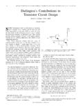
1 Most popular OP-AMP (operational amplifier) ICs such as the 741, CA3140, and LF351, etc. give anoutput voltage that is proportional to the differencebetween the IC s two input pin voltages, and are thus known asvoltage-differencing amplifiers or VDAs. There are, however,two other basic types of op-amps that are in common use; oneof these is the type that gives an output voltage that is propor-tional to the difference between the currentsapplied to its twoinput terminals, and is thus known as a current-differencingamplifier or CDA. This type of OP-AMP was described in depthin the UNDERSTANDING and USING Norton OP-AMP ICs two-part mini-series published in this magazine. The third type ofop-amp is known as an operational transconductance amplifi-er or OTA, and acts as a variable-gain of the best known OTA ICs is the CA3080, which isof particular value in making voltage- or current-controlledamplifiers, or micro-power voltage comparators or oscillators,etc.
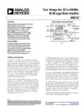
2 OTAs have operating characteristics very different fromconventional op-amps, and Figure 1illustrates the major dif-ferences between these two types of 1(a)shows the basic symbol and formulas of theconventional OP-AMP , which is essentially a voltage amplifyingdevice. It has differential input terminals and gives an output ofAOx (e1- e2), where AOis the open-loop voltage gain of theop-amp and e1and e2are the signal voltages at the non-invert-ing and inverting input terminals, respectively. Note that theopen-loop voltage gain of this OP-AMP is fixed, and the devicehas a high input impedance and a low output 1(b)shows the basic symbol and formulas of anOTA, which is essentially a voltage-to-current amplifier. It hasdifferential voltage input terminals (like a conventional OP-AMP ) but as indicated by the constant-current symbol on itsoutput these input voltages produce a high-impedance out-put in the form of a current with a value of gm x (e1- e2),where gm is the transconductance or voltage-to-current gain ofthe device and can be controlled by (and is directly proportion-al to the value of) an external bias current fed intothe Ibiasterminal.
3 In the CA3080, Ibiascan be variedfrom A to 1mA, giving a 10,000:1 OTA is a very versatile device. It can, forexample, be made to act like a normal OP-AMP bysimply wiring a suitable load resistance to its out-put terminal (to convert its output current into volt-age). Again, since the magnitude of Ibiascan easilybe controlled by an external voltage and a seriesresistor, the OTA can easily be used as a voltage-controlled amplifier (VCA), oscillator (VCO), or fil-ter (VCF), etc. Note that the total current consump-tion of the CA3080 OTA is only twice the Ibiasvalue(which can be as low as A), enabling thedevice to be used in true micro-power best known current-production versions of the OTA are theCA3080 and the LM13700. The LM13700 is a dual second-generation OTA with built-in output-buffer stages, and will befully described next month.
4 The CA3080 is a first-generationOTA, and is the exclusive subject this month. Figure 2(a)shows the connections of the eight-pin DIL E version of theCA3080. Figure 2(b)shows its internal circuit, and Figure 3lists its basic parameter BASICSThe CA3080 is a fairly simple device and consists of onedifferential amplifier and four current mirrors. Figure 4showsthe basic circuit and formulas of its differential amplifier. Itsemitter current (Ic) is equal to the sum of the two collector cur-rents (Iaand Ib). When Vinis zero, Iaand Ibare equal and havea value of Ic/2. When Vinhas a value other than zero (up to 25mV maximum), the Iaand Ibcurrents differ and produce anIb- Iavalue of Vinx gm, where gm is the OTA s transconduc-tance, is directly proportional to Ic, and has a typical mhovalue of about 20 x Figure 4circuit is of little value onits own and, in the CA3080, it is turned to good use by USING asimple current mirror to externally control its Icvalue (and thusthe gm of the OTA), and by USING another three current mir-rors to extract the difference between the Iaand Ibcurrents andmake this difference current available to the outside world.
5 Acurrent mirror (CM) is a three-terminal circuit that, when pro- UNDERSTANDING ANDUSING OTA OP-AMP ICs by Ray Marston58 NUTS &VOLTSE verything For ElectronicsTake a look at Operational Transconductance Amplifier (OTA) OP-AMP principles andat practical CA3080 OTA circuits in this opening episode of a two-part 2003 Figure 1. A conventional OP-AMP (a) is a fixed-gain voltage-amplifyingdevice. An OTA (b) is a variable-gain voltage-to-current (a) of theeight-pin DIL E version ofthe CA3080,and (b) itsinternal 1vided with an external input biascurrent, produces an in-phasecurrent of identical value at itsoutput terminals, as shown inFigure 5. Some CMs act as cur-rent sinks, as shown in Figure5(a)and others as currentsources, as in Figure 5(b). Whena CM source and a CM sink areconnected as shown in Figure 6and powered from split supplyrails, they generate a differential(Isource- Isink) current in anyexternal load connected to the 0 Vrail.
6 Figure 7shows the actual cir-cuits of two sink-type current mir-rors. In the simplest of these(Figure 7(a)), a diode-connectedtransistor (QA) is wired across thebase-emitter junction of a second,closely matched, transistor that isintegrated on the same chip. Theinput current is fed to the bases ofboth matched transistors and thusdivides equally between these transistors havecurrent gains of x100 and areeach drawing base currents of5 A. In this case, they each drawcollector currents of 500 A. Note, however, that the QA collec-tor current is drawn from the circuit s input current, which thusequals 500 A plus (2 x 5 A), or 510 A, and that the QB collec-tor current is the output or mirror current of the circuit. The input and output currents of this circuit are thus almostidentical (within a few percent), irrespective of the input currentmagnitude.
7 In practice, the input /output current ratio of theabove circuit depends on the close gain matching of the twotransistors, and this can actually vary by several percent. Figure7(b)shows an improved current mirror circuit that is less sensi-tive to current gain variations and also gives an improved(greater) output 8shows how the differential amplifier and four cur-rent mirrors are interconnected in the CA3080 to make a prac-tical OTA. Bias current Ibiascontrols the emitter current, andthus the gm, of the Q1-Q2 differential amplifier via CMC. Thecollector currents of Q1 and Q2 are mirrored by CMA and CMBrespectively, and then fed into the bias and sink terminalsrespectively of CMD, so that the externally available output cur-rent of the circuit is equal to IB- IA.
8 Looking back to Figure 2(b),which shows the actual internal circuit of the CA3080, the read-er should now have little difficulty in working out the functionsof individual circuit elements. Q1 and Q2 form the differentialamplifier, with D1-Q3 making up CMC of Figure 8, and CMDcomprising D6-Q10-Q11. Current mirrors CMA (Q4-Q5-Q6-D2-D3) and CMB (Q7-Q8-Q9-D4-D5) are slightly more complex, USING Darlington pairs of transistors, plus speed-up diodes, toimprove their FINER POINTSAll the major operating parameters of the CA3080 areadjustable and depend on the value of Ibias. The maximum(short circuit) output current is equal to Ibias, the total operatingcurrent of the OTA is double the Ibiasvalue, and the input biascurrents drawn by pins 2 and 3 typically equal transconductance (gm) and the input and outputimpedance values also vary with the Ibiasvalue, as shown in thegraphs in Figure 9, which show typicalparameter values when the IC is driven from split 15V suppliesat an ambient temperature of +250C.
9 Thus, at a bias current of10 A, gm is typically 200 mho, and input and output imped-ances are 800k and 700M, respectively. At 1mA bias, the valueschange to 20mmho, 15k, and 7M0, available output voltage swing of the IC depends onthe values of Ibiasand any external load resistor connected tothe OTA output. If the load impedance is infinite, the output canswing to within 1V5 of the positive supply rail and to within 0V5of the negative rail. If the impedance is finite, the peak outputvoltage swing is limited to Ibiasx RL. Thus, at 10 A bias with a100k load, the available output voltage swing is a mere slew rate (and bandwidth) of the IC depend on thevalue of Ibiasand any external loading capacitor connected tothe output. The slew rate value, in volts per microsecond, equalsIbias/CL, where CLis the loading capacitance value in pF, andthe Ibiasvalue is in microamps.
10 With no external loading capac-itor connected, the maximum slew rate of the CA3080 is about50V/ CIRCUITSThe CA3080 is a very easy IC to use. Its pin 5 Ibiasterminalis internally connected to the pin 4 negative supply rail via abase-emitter junction, so the biased voltage of the terminal is59 APRIL 2003 Figure circuitand formulasof the differentialamplifier ofthe representing (a) a current-mirror sink and (b) a current-mirror two current mirrors are wiredas shown, they generate a differential current inan external 7. Examples of simple sink-type current voltage range+4V to +30V DC or 2V to 15 VMax. differential input voltage 5 VPower dissipation 125mW maximumInput signal current1mA maximumAmplifier bias current2mA maximumOutput short-circuit duration IndefiniteForward transconductance, gm 9600umho typicalOpen loop bandwidth2 MHzUnity-gain slew rate50V/uSCommon-mode rejection ratio 100dB typicalFigure 3.