Transcription of Understanding Capacitor Inductance and …
1 Note# 3009,V1, 2/27/06 Page 1 of 21 Understanding Capacitor Inductance and measurement in Power Bypass Applications Summary Power supply bypass is a critical function in all electronics. High frequency Capacitor performance depends on the mounted Inductance of the bypass Capacitor network. The number of capacitors needed to reach a given performance target is directly proportional to the mounted Inductance of each individual Capacitor . The total number of vias needed is proportional to device Inductance multiplied the number of vias that attach each part. When mounted with well-designed attachment vias, X2Y capacitors often replace four or five times as many conventional capacitors .
2 Because X2Y capacitors utilize vias more efficiently than conventional capacitors ; X2Y capacitors often reduce the total bypass Capacitor via count anywhere from 30-60%. This paper explains the elements of Capacitor Inductance , and how to accurately characterize bypass capacitors for power supply bypass applications. Introduction Bypass capacitors1 support power supply voltage at medium to high frequencies: from a low-frequency cut-off with the voltage regulator module ( 100kHz to 1 MHz typical ), to a high frequency cut-off with the PCB planes, ( several hundred MHz typical ). Within their range of operation, ceramic capacitors exhibit a well-known V shaped response curve.
3 Capacitance dominates impedance at frequencies below the series resonance of the mounted part. Around series resonance, the Capacitor ESR sets the minimum impedance, while above the series resonance, the mounted Inductance sets device impedance. The mounted Capacitor Inductance sets both the SRF, and the device performance above the SRF. The mounted Inductance of a single Capacitor sets the number of capacitors needed to hit a given impedance target up to the high frequency transition to the PCB planes. Similarly, the mounted Inductance multiplied by the number of vias used by each Capacitor determines the total number of vias in the bypass network.
4 X2Y capacitors excel both in mounted Inductance and superior ( lower ) mounted ESL * via count products. These facts are born out through carefully designed and verified device and application characterization fixtures. Simply put, proper application of X2Y capacitors results in a bypass network with both the fewest total capacitors , and fewest vias compared to any other Capacitor in the market today. 1 Bypass capacitors are so named as over the frequency range that they are effective, most load current diverts through the capacitors , bypassing the rest of the power system.
5 DISCLAIMER: Information and suggestions furnished in this document by X2Y Attenuators, LLC are believed to be reliable and accurate. X2Y Attenuators, LLC assumes no responsibility for its use, nor for any infringements of patents or other rights of third parties which may result from its use. X2Y is a registered trademark. All other brand or product names mentioned in this document are trademark or registered trademarks of their respective holders. These notes are subject to change without notice. Copyright X2Y Attenuators, LLC all rights Capacitor Inductance and measurement in Power Bypass Applications Bypass Capacitor Behavior To a reasonable approximation, bypass capacitors may be modeled as three significant elements all in series: device capacitance, effective series resistance, ESR, and mounted effective series Inductance , ESL.
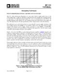
6 At all frequencies we are concerned with the parameter that limits the capacitors ability to shunt current. At high frequency, barring very small capacitance values, it is the ESL that defines ( limits ) bypass performance. This can be readily understood by first modeling capacitors with zero ESL, as shown by the blue RC Response curve in Figure 1. Figure 1, Bypass Capacitor Impedance vs. Frequency, MHz As Figure 1 shows, capacitance dominates impedance below the RC corner, as 1/jwC, while the ESR sets the impedance above the corner. More capacitance shifts the corner frequency down. It does not reduce impedance beyond the corner.
7 We can scale impedance above the corner down only by paralleling more components, or finding components with a lower ESR. Now, let s turn our attention to the effects of ESL. Changes in current induce counter EMFs that oppose the respective current change. For a given peak-to-peak current, the rate of change, and therefore the opposition to current flow, is proportional to frequency. Whereas capacitive reactance decreases with frequency, inductive reactance increases. Note# 3009, V1, 2/27/06 Page 2 of 21 Understanding Capacitor Inductance and measurement in Power Bypass Applications Capacitive current leads signal voltage by 90 degrees, while inductive current lags by 90 degrees.
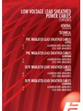
8 When the magnitudes are similar, the net reactance falls quickly. The point where the magnitudes match and completely cancel is the Capacitor series resonant frequency, SRF. At the SRF, Capacitor impedance is its minimum, equal to the device ESR, also shown in Figure 1. Above the SRF, the capacitive reactance continues to fall, and the inductive reactance continues to rise. Phase cancellation quickly diminishes until the Capacitor impedance appears almost completely inductive. Even though the Capacitor behavior is inductive above the SRF, the Capacitor still presents a shunt across the power system, lowering impedance by diverting current away from the rest of the power system.
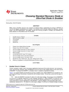
9 Because the impedance is inductive, the amount of current each Capacitor diverts diminishes with rising frequency. To illustrate, we show the same Capacitor from Figure 1, but raise the ESR to Ohms as shown in Figure 2. We may parallel some number of these high capacitors in order to hit desired system impedance over the broad frequency range 500kHz to 500 MHz. The green trace plots Capacitor response from Figure 1. The low ESR Capacitor impedance remains everywhere equal or below that of the high ESR Capacitor . Since, the high ESR Capacitor remains effective diverting current over this broad frequency range, we must similarly conclude that the low ESR Capacitor is at least as effective over the same frequency range.
10 Bypass capacitors remain effective even in the inductive region above the SRF. What limits the frequency range at which the capacitors remain significant is the amount of plane capacitance in the plane cavity to which the capacitors attach, the Inductance of each attached Capacitor , and the spatial density of the capacitors . At a sufficiently high frequency, the inductive reactance of the bypass Capacitor network crosses the magnitude of the capacitive reactance of the power / ground plane cavity the network attaches to. Beyond the discrete bypass network to power cavity crossover frequency, load currents divert mostly through the plane cavity crossover frequency is a function of the plane cavity height, dielectric, mounted Inductance of each bypass Capacitor , and the average density of bypass capacitors attached to the PWB.