Transcription of Understanding electromagnetic compliance tests in digital ...
1 Understanding electromagnetic compliance tests in digital isolators Sarangan Valavan Applications Engineer Texas Instruments Choosing the right digital isolator requires a clear Understanding of electromagnetic compliance test methods and results, after accounting for common performance improvement techniques. For a system designer working with high voltage and high-voltage isolation, one of the most important tasks is to choose the right digital isolator for the system. electromagnetic compatibility (EMC) is a key consideration on which this choice hinges. An in-depth Understanding of how the different EMC tests are performed help in making this decision correctly. It also helps in differentiating the isolator's true performance in the actual system versus the claimed performances on a far from practical test setup.
2 This paper discusses EMC standards and test setups for the relevant EMC parameters. In the exacting conditions of an industrial There are standards and regulations that must environment, the reliability and longevity of a be met to ensure that the digital isolators aid the communication link relies heavily on the individual smooth functioning of the intended final system. system component's robust EMC. digital isolators In this document we describe some of these key play a major part in ensuring continued, reliable isolation and EMC test and discuss the performance performance of these systems even during of reinforced digital isolators. extremely harsh stresses like lightning strikes, high electrostatic discharges, and electromagnetically- EMC test setup vs.
3 A typical system coupled, high-energy transients from neighboring Performance in EMC tests can appear to be better, high-power systems, and so on. Hence, assessing artificially, by using costly or impractical board level the performance of these digital isolators during implementations. such stresses is a critical but challenging part of Typical methods include: choosing the right isolator. Adding large and expensive high-voltage capacitors A clear Understanding of the setup in which these across the isolation barrier. tests are done is important to avoid common Complex PCB plane designs intended to increase mistakes or pitfalls that can affect the results. capacitance between both sides of the isolation barrier.
4 Performing tests on multiple custom boards, each optimized for one of the above tests . For example, using a small two-layer coupon card for radiated susceptibility tests and a large board with expansive planes for across the barrier ESD tests . Though such methods can be considered for the final system design, they should not be employed when evaluating/comparing the performance of a digital isolator by itself. The above methods, in one way or the other, either block or divert the actual stress from reaching the isolators. Understanding electromagnetic compliance tests in digital isolators 2 November 2014. Such methods, instead of exposing the true Electrostatic discharge immunity performance of the isolator, are designed to protect Electrostatic discharge (ESD) is the transfer of it from the full force of the stress.
5 This is where a charge between two objects at different potential careful review of test setups for EMC tests becomes and is caused by contact or an induced electric critical for a system designer. field. The transfer is characterized by a very high A good EMC test setup should: current in a short duration. The objects become Employ simple PCB design practices that are already in charged by a mechanism called tribo-charging or common use tribo-electric charging. This happens whenever Have basic components and blocks seen in most common two dissimilar materials make contact and then are digital isolator systems separated. The charging can be greatly increased Not be architected to make a device pass a standard test, when one of the materials is an insulator.
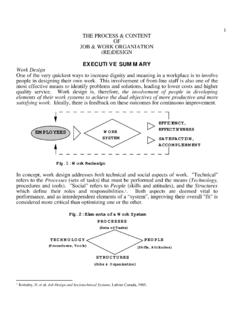
6 But to identify its inherent capability Not be changed from one test to another unless the In many systems, board-level ESD protection circuits standard requires it like TVS diodes are employed. But for digital isolators, ESD performance for strikes across the isolation EMC/EMI board barrier is a key metric as board-level ESD protection The ISO7842 EMC / electromagnetic interference devices cannot be employed. This is because a major (EMI) board shown in Figure 1, (block diagram) portion of the energy of an across the barrier strike and Figure 2 (photograph) meets the above appears as a common mode for an ESD protection expectations. We used this board to evaluate EMC. device sitting on one side of the isolation barrier.
7 JEDEC standard models such as human body model (HBM), charged device model (CDM) and Regulator ISO 7842 DW Regulator VCC 1= V to VCC 2= V to 6V to 30 V. 6V to 30 V. 1 16. `. GND 1 2 15 GND 2. INA 3 14 OUTA. INB 4 13 OUTB. OUTC 5 12 INC. OUTD 6 11 IND. EN 1 7 10 EN 2. GND 1 8 9 GND 2. Figure 1. Block diagram of an EMC/EMI evaluation board EFT strike points Adjustable voltage regulators Figure 2. Block diagram of an EMC/EMI. evaluation board ESD strike points digital Isolator Understanding electromagnetic compliance tests in digital isolators 3 November 2014. machine model (MM) are used to assess device-level The susceptibility threshold, or limit, of a system ESD robustness, while the IEC 61000-4-2 standard is the field strength that induces sufficiently defines the system-level ESD performance test.
8 High current to cause the system to no longer The graph in Figure 3 compares the stress seen by operate acceptably. Thus, at field levels below equipment under test (EUT) when subjected to ESD the susceptibility threshold, the device operates events as recommended in the above models. acceptably. At field levels above the susceptibility 48 threshold, the device does not operate acceptably. 8 kV IEC model: 30 A PK with 1 ns duration followed by a 16 A PK pulse with 50 ns duration This limit for a given system typically varies as a 36 function of frequency. 2 kV CDM : up to 5 A PK with 1 ns duration Currnet, Ipp(A). Radiated susceptibility tests are performed on 24. 2 kV HBM : A PK with 150 ns duration a device to determine whether the device is susceptible to electromagnetic fields having specified 12.
9 Amplitude over a specified frequency range. If the 0. device operates acceptably as the field is applied 0 50 100. Time (ns). and swept over the specified frequency range, the device is considered to have passed. If not, it has Figure 3. Comparison of stress due to different ESD models failed. In many cases, a device that is adversely IEC-61000-4-2 defines two discharge modes and affected by the field returns to normal operation four test levels of performance defined in when the field is removed. Typically, radiated EMI. Table 1 below. occurs when the dimensions of the equipment Contact discharge Air discharge being examined are of the similar magnitude as the Level Test voltage kV Level Test voltage kV wavelength of the interfering signal.
10 1 2 1 2. IEC-61000-4-3 is the relevant standard for this test. 2 4 2 4. It is performed in a semi-anechoic chamber similar 3 6 3 8. to the radiated emissions setup with only the signal 4 8 4 15. X (1) Special X (1) Special chain reversed. The frequency range is swept from 80 to 1000 MHz. The modulation is 80 percent AM. Note 1: X is an open level. The level must be specified in the dedicated equipment specification. If higher voltages than those with a 1 kHz sine wave. The stress field levels up to are specified, special test equipment may be required. which the system operates as expected is quoted Table 1. IEC 61000-4-2 performance levels as the system performance. The various test levels Radiated susceptibility test for 80 -1000 MHz as prescribed in the standard are Radiated susceptibility is a measure of the system's shown in Table 2.