Transcription of UNIT 22: PROGRAMMABLE LOGIC CONTROLLERS …
1 unit 22: PROGRAMMABLE LOGIC CONTROLLERS . unit code : A/601/1625 QCF level: 4 Credit value: 15. TUTORIAL OUTCOME 2 Part 2. This work covers part of outcome 2 of the Edexcel standard module. The material is quite suitable for anyone wishing to study this interesting subject. This tutorial requires basic mathematical skills and a reasonable knowledge of digital electronic terminology. An industrial background will also be of great benefit to students. Obviously, access to suitable computer software such as Pneusim Pro . or Bytronics simulation software will be a great help. SYLLABUS. 2 Understand PLC information and communication techniques Forms of signal: analogue (0-10 V dc. 4-20 digital Digital resolution and relationships: 9-bit; 10-bit 12-bit Number systems: decimal; binary; octal; hexadecimal; Binary-Coded Decimal (BCD). Evaluate communication standards: comparison of typical protocols used in signal communication Evaluate networking methods and standards: master to slave; peer to peer; ISO; IEE; MAP.)
2 LOGIC functions: writing programmes using LOGIC functions based on relay ladder LOGIC (AND; OR;. EXCLUSIVE OR; NAND; NOR). Learning outcomes Assessment criteria for pass On successful completion The learner can: of this unit a learner will: L02 Understand PLC evaluate the different forms of signal used in PROGRAMMABLE information and LOGIC control communication describe the resolution and relationship between analogue techniques inputs and outputs and word length express numbers using different number systems describe typical protocols used in signal communication and evaluate networking methods and networking standards CONTENTS. 1. COMMUNICATION. RS232. RS422. IEEE 488. Industrial Applications ISO, IEEE, MAP. Networks LAN, Ethernet, Intranet, Extranet Instrument Telemetry 1. 1. COMMUNICATION. When you come to a set of traffic lights, you observe the colour and interpret red as meaning stop and green as go. In Britain we also have orange which gives a warning of change but it does not take priority over stop or go.
3 This is PROTOCOL and other countries have a different protocol so we must be very careful to use the correct protocol. Another example of protocol is shaking the head to mean no and nodding to mean yes. There are countries where the opposite applies. When you use a computer or mobile phone to communicate with someone else, the data is transmitted digitally. Each end of the communication link has a MODEM (Modulator/Demodulator). to encode or decode the digital data. The transmission may be through a radio link, through copper wires or optic fibres. (see outcome 1). More complex systems such as used in industry or at a telephone exchange, send multiple channels in both directions and in order to do this they need a multiplexer. When sending data the multiplexer mixes the channels together to form one channel. The modem sends them (a bit of each at a time). When receiving signals, the process is reversed. Signals are needed to tell the equipment when to send and when to receive. Other signals are needed to synchronise the signals at both ends.
4 This is another example of protocol. Figure 1. On electronic equipment we find many types of standard plugs and sockets. Here are 3 popular types. Figure 2. These are used typically on printers, scanners, disc drives and COM ports. They may be attached to all forms of industrial equipment as well as computers. Some carry SERIAL transmission and other PARALLEL transmission. Serial transmission means the data is sent one bit at a time while parallel transmission might send a whole word in one go. Digital data transmission is not covered in detail here. 2. Industrial systems also use many methods of linking equipment such as PLCs, computers, sensors, monitors and automated machinery. In order that equipment can be interconnected physically, the sockets, plugs and wiring connections must be the same for everyone otherwise you could not work with each other. The standards covering a range of sizes and applications are numerous. Here are details of some of the standard forms of links and protocols.
5 RS232. RS-232 is a system originally developed for linking telly printers and is a relatively slow serial data transmission system. The standard is for the physical interface and protocol used in many links from computers to industrial electronic equipment. The system has undergone many updates and RS232C. is the current one. Typical uses are in computer modems and linking any device using serial communication. Somewhere in the equipment is a Universal Asynchronous Receiver/Transmitter (UART) chip. The data is transmitted to a modem (or other serial device) from its Data Terminal Equipment (DTE) interface. Data inside equipment flows along busses (Data and Address busses). and these are parallel circuits. Serial devices can only handle one bit at a time. The UART chip converts the groups of bits in parallel to a serial stream of bits. The 9 pin (DB9) and 25 pin (DB25) sockets are shown below with their connections for RS 232. Figure 3. Here are the pin connections for joining the plugs without explanation.
6 DB-9 PIN (Male) FUNCTION ABBREVIATION. 1 --------------------------- Data Carrier Detect CD or DCD. 2 ------------------------------ Receive Data RD or RX. 3 ---------------------------- Transmitted Data TX or TD. 4 ---------------------------- Data Terminal Ready DTR. 5 ------------------------------ Signal Ground GND. 6 ------------------------------ Data Set Ready DSR. 7 ------------------------------ Request To Send RTS. 8 ------------------------------ Clear To Send CTS. 9 ------------------------------ Ring Indicator RI. DB-25 PIN (Male) FUNCTION ABBREVIATION. 1 ---------------------------- Chassis/Frame Ground GND. 2 ------------------------------ Transmitted Data TX or TD. 3 -------------------------------- Receive Data RX or RD. 4 ------------------------------ Request To Send RTS. 5 ------------------------------- Clear To Send CTS. 6 ------------------------------- Data Set Ready DSR. 7 ------------------------------- Signal Ground GND. 8 ---------------------------- Data Carrier Detect DCD or CD.
7 9 ------------------------- Transmit + (Current loop) TD+. 11 ------------------------ Transmit - (Current Loop) TD- 18 ------------------------- Receive + (Current Loop) RD+. 20 --------------------------- Data Terminal Ready DTR. 22 ----------------------------- Ring Indicator RI. 25 ------------------------- Receive - (Current Loop) RD- 2in to 9 pin 9 pin to 9 pin Figure 4. 3. RS422. The RS422 is similar to the RS232 but it more suited to transmissions over long cables. Converters are devices which allow different systems such as the RS232 and 422 to communicate even though the protocols are different. IEEE 488. This is the main standard for parallel data transmission such as used on the printer ports (LPT) of computers. Usually you find the DB25 at the computer end and the Centronics type (36 pins) at the other end. These are widely used to link industrial equipment using digital technology. When the Centronics parallel interface was first developed, the main peripheral was the printer.
8 Since then, portable disk drives, tape backup drives, and CD-ROM players are among devices that have adopted the parallel interface. These new uses caused manufacturers to look at new ways to make the Centronics parallel interface better. In 1991, Lexmark, IBM, Texas instruments, and others met to discuss a standard that would offer more speed and bi-directional communication. Their effort and the sponsorship of the IEEE resulted in the IEEE 1284 committee. The IEEE 1284. standard was approved for release in March, 1994. DB-25 PIN (Female) SIGNAL. DB-25 MALE CONN DB-25 FEMALE CONN. 1 ------------------------------- > STROBE *. 2 ------------------------------- > DATA 0. 3 ------------------------------- > DATA 1. 4 ------------------------------- > DATA 2. 5 ------------------------------- > DATA 3. 6 ------------------------------- > DATA 4. 7 ------------------------------- > DATA 5. 8 ------------------------------- > DATA 6. 9 ------------------------------- > DATA 7. 10< ------------------------------ ACK *.
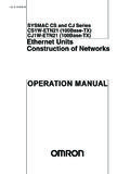
9 11< ------------------------------ BUSY. 12< ------------------------------ PAPER END. 13 ------------------------------ SLCT (select). 14 ------------------------------ >AUTOFEED *. 15< ------------------------------ ERROR *. 16 --------------------------->INITIALIZE PRINTER *. 17 ------------------------------- SLCTIN (select in). 18 thru 25 ----------------------- GND. 4. INDUSTRIAL APPLICATIONS. Manufacturing And process industries use similar methods of communication to link the systems to each other. A typical manufacturing system is illustrated below. Various machines are controlled by individual PLCs and these are linked to each other and to the main computer. Figure 5. The computer at the top is the MASTER and the plc are the SLAVES. Communication between them is master to slave or slave to master. Communication between the PLCs is peer to peer. There are various protocols and standards laying down the way they communicate such as: ISO International Standards Organisation IEEE Institute of Electrical and Electronic Engineers MAP Manufacturing Automation Protocols This is a token-passing local area network configuration adopted by General Motors for factory automation.
10 NETWORKS - Definitions LAN Local Area Network ETHERNET. This is a very common method of networking computers in a LAN using copper cabling. Ethernet will handle about 10,000,000 bits-per-second and can be used with almost any kind of computer. INTRANET. This is a general name for networks linking computers within a private organisation such as colleges, businesses and government departments. They use standard network technologies like Ethernet and web servers. Users connected to the intranet often have access to the internet but a firewall prevents external users accessing it. Sometimes it may allow access to an extranet to provide controlled access to some outsiders ( other government departments). EXTRANET. An extranet is a private network that allows limited access to specified users. It uses the Internet for these links. A typical example is a bank with internet access for customers using secure protocols. 5. INSTRUMENT TELEMETRY. On a complex process plant, the need to transmit many process variables plus the state of many switches (on or off) has led to the use of TELEMETRY SYSTEMS.