Transcription of Universal Eight Zone Remote Point Module …
1 Installation Instructions4208U Universal Eight Zone Remote Point ModuleN8215V2 11/96 FEATURESThe ADEMCO 4208U Remote Point Module (RPM) is an8-zone expander which allows use of the availableexpansion zones provided by ADEMCO controls thatsupport polling loop devices. Characteristics of thisdevice include: Can be optionally powered from an external DCpower supply to reduce current draw from thepolling loop Uniquely identifies 8 EOLR supervised zones (all zones use 10k resistors, supplied) DIP Switches can be used to set zone numbersor serial numbers When used in the serial number mode, eachserial number in the selected group can beassigned to any zone number. Loops A&B can be programmed for fast (10msec) response Tamper protectedMOUNTING1.
2 Power should be disconnected before sure to mount the 4208U beforemaking any wiring mounted inside the cabinet with the control, the4208U should be mounted horizontally and does notneed to be tamper protected. Insert two screws into theraised metal tabs leaving the heads app. 1/8 exposed,then hang the 4208U using the two slots on the mounted in the cabinet, the 4208U does not needto be tamper protected or have the cover on, except inUL mounted remotely, the 4208U can be mountedhorizontally or vertically. Tamper protection should beenabled via the DIP switches and the cover put on. Iftamper protection is required, be sure to enable theexpansion zone tamper option at the control (programfield *24=0).
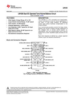
3 Tamper protection is provided by a magneton the cover and a reed switch mounted on the device. Ifthe cover is opened, a trouble will be sent to the controlfor every active zone on the 4208U loop and protection loop wires can be brought ineither through the back or front of the unit by removingthe knockouts. Use 22 gauge twisted pair wire for pollingloop connections. All protection loops use 10k EOLresistors (included). A maximum resistance of 300 ohmsis allowed on protection loops (excluding EOLR). SeeFigure 2 for all connections. Keep in mind that connec-tions to the polling loop are always required, while powersupply connections are SWITCH SETTINGSZone Assignment Mode:In the zone assignment mode, the DIP Switches on the4208U are used to assign the unit to a group of 8consecutive zones .
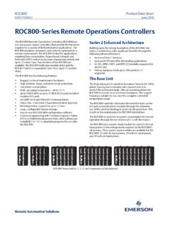
4 These zone numbers, oncedesignated for the 4208U, cannot be used for anythingelse, even if you don t use all 8. Follow the steps belowusing Table 1 for DIP Switch settings:Serial Number Mode:In the serial number mode, the DIP Switches on the4208U are used to assign the unit to a group of 8 serialnumbers. You can assign any serial number to anyzone number (except hardwire zone numbers on thecontrol), and you do not lose zone numbers if you don tuse all Eight loops on the 4208U. Follow the steps belowusing Table 2 for DIP Switch settings:Set the DIP Switches on the 4208U as instructed below(see Figure 1) fast/slow response for loops A andB using DIP Switch 1: Fast = OFF(10msec); Slow = ON (400msec).
5 Mode of operation (serial number orzone assignment mode) using DIP Switch6: Serial Number mode = ON; ZoneAssignment mode = 1: DIP Switch the group setting using Dip switches2,3,4,and 5. See Table 1 for zoneassignments or Table 2 for serial numberassignments. If using more than one4208U, be sure to set each one to adifferent group Switch 7: Not Used, set to the 4208U Tamper Protectionsetting using DIP Switch 8: TamperDisabled = ON; Tamper Enabled = will report for every active zone onthe 4208U UL Listed Commercial Burglary,the 4208U must be tamper protected ormounted in a tamper protected all UL installations, the cover mustbe on the unit, even if the unit ismounted in the control s Table 1: 4208U Zone AssignmentsFigure 2: Summary of ConnectionsTable 2: 4208U Serial Number Assignments-2-}OPTIONAL}12 VDCPROGRAMMINGWhen setting the 4208U to a group of zone numbers,each zone must be programmed as follows.
6 On 4140 XMP and earlier controls, these zones mustbe programmed as Left Loop Polling Loop Vista-40 and later controls, these zones must beprogrammed in the #93 Menu Mode ZoneProgramming as INPUT TYPE 7 --DIP Switch typepolling loop device (DP).When setting the 4208U to a group of serial numbers,each zone must be programmed as INPUT TYPE 6 --SL (Serial Number Polling Loop Device). Loops can belearned in any order and assigned to any legitimate prompted to Learn the serial number for aparticular zone, you may either enter it manually throughthe keypad or through V-Link, or learn it in bymomentarily faulting (shorting) the terminals of that zoneas required by the control.
7 If entering a serial numbermanually through the keypad, enter it and press * toadvance to the next prompt, which will ask you for theloop number. Enter a 1 for each serial number learning or entering a serial number, and the message Duplicate of Zone XX is displayed, another device withthat same serial number is aready in the system. In thatcase, use a different serial number group setting on the4208U. VERIFICATION OF PROGRAMMINGTo verify proper programming, the following test shouldbe sure to enable expansion zone tamper protectionat the control (program field *24 = 0). DIP Switch 8 to OFF (tamper enabled). the 4208U cover and clear the keypad ofany faulted the 4208U s cover and verify (on thekeypad) that only the zones you designated for this4208U are indicating a check (or trouble) condition.
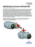
8 SPECIFICATIONSP hysical:Width: 6-7/6 (163mm)Height: 4-1/4 (108mm)Depth: 1-1/4 (32mm)Electrical:Polling loop input: - 14 VDCC urrent draw: max. external power and polling loop (see Table 3)External Power Input (optional):12 VDC @28mA (from control panel s auxiliary power)Sensor Loop Response:Slow: 400msec (all loops)Fast: 10msec (option for loops A and B)Sensor Loop Current: (@ polling loop input= 11 VDC, no external power input) (normal) (shorted)Sensor Loop Max. Resistance:Up to 300 ohms of wire resistance + 10k learning a serial number by faultingits associated loop, be sure that otherpolling loop devices are not activated,as they may interfere with the devicebeing Input Source(Input Voltage: 11 - 14 VDC)Current Draw (all zones shorted)From Polling LoopFrom External PowerPolling Loop mAPolling Loop and External Power mA28 mATable 3: Current Draw Calculations-3-For UL Listed Commercial Fire Usage:Use contacts.
9 Style B supervise these loops usingModel #EOL100 fire listed 10k EOLRs (purchased separately).For UL Listed Commercial Burglary Usage:Use: or contacts. Supervise using EOLRs Limited WarrantyAlarm Device Manufacturing Company, a Division of Pittway Corporation, and its divisions, subsidiaries and affiliates ("Seller"),165 Eileen Way, Syosset, New York 11791, warrants its products to be in conformance with its own plans and specifications andto be free from defects in materials and workmanship under normal use and service for 24 months from the date stamp control onthe product or, for products not having an Ademco date stamp, for 12 months from date of original purchase unless the installationinstructions or catalog sets forth a shorter period, in which case the shorter period shall apply.
10 Seller's obligation shall be limited torepairing or replacing, at its option, free of charge for materials or labor, any product which is proved not in compliance withSeller's specifications or proves defective in materials or workmanship under normal use and service. Seller shall have noobligation under this Limited Warranty or otherwise if the product is altered or improperly repaired or serviced by anyone otherthan Ademco factory service. For warranty service, return product transportation prepaid, to Ademco Factory Service, 165 EileenWay, Syosset, New York ARE NO WARRANTIES, EXPRESS OR IMPLIED, OF MERCHANTABILITY, OR FITNESS FOR A PARTICULARPURPOSE OR OTHERWISE, WHICH EXTEND BEYOND THE DESCRIPTION ON THE FACE HEREOF.