Transcription of USB Interface II - microHAM
1 microHAM 2016 All rights reservedUSB Interface IImicroHAMfax: +421 2 4594 5100e-mail: March 20161microHAM 2016 All rights reservedTABLE OF CONTENTSCHAPTER PAGE1. FEATURES AND FUNCTIONS ..32. IMPORTANT WARNINGS .. 33. PANEL DESCRIPTION .. 4 Rear Panel .. 4 Front Panel .. 5 Preparing for 5 Macintosh (OS X) 6 Windows .. 6 Installing microHAM USB Device Router ..6 Configuring microHAM Device Router ..6 Creating and Using Virtual Ports .. DEVICE ROUTER .. 9 Menu: Router .. 9 Menu: Preset .. 10 Menu: Device .. 11 Menu: Virtual Port .. 12 Menu: Help .. 12 Ports 13 Radio Port .. 13CW 14 PTT 14 Squelch Port .. 146. SETTING AUDIO LEVELS .. 157. SYSTEM CONSIDERATIONS .. 168. PACKAGE CONTENTS .. 179. WARRANTY ..1710. SPECIFICATIONS .. 18 Hardware Specifications .. 18 DECLARATION OF CONFORMITY .. 19 APPENDIX A - DB15 RADIO CONNECTOR.
2 20 APPENDIX B FSK WITH 21 APPENDIX C RFI Considerations .. 22 APPENDIX D Cables and Bridges .. 232microHAM 2016 All rights reserved1 - FEATURES AND FUNCTIONS No Serial or Parallel port necessary, just one USB port Complete "Computer <-> Radio" isolation bidirectional transformer isolation of audio signals optical isolation of ALL digital signals: Radio Control, CW, PTT, FSK Compatible with all MS Windows based logging or control software the special microHAM "USB Device Router" program creates virtual COM ports for full operation with standard Windows applications. customizable presets allow instantly changing USB Interface II parameters to match the program currently in use Integrated computer control port for all radios CI-V, FIF-232, IF-232, RS-232 fully supports Icom, Kenwood, TenTec, Yaesu and other radios no separate level converter required Squelch input for additional software control Strong RFI immunity integrated chokes and filters for best RFI immunity advanced shielding and circuit design for RFI product suppression Connections.
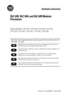
3 Computer USB Radio DB15 Sound Card 2 x (1/8 ) Front panel LEDs for easy visual feedback of CW, PTT, SQL, POWER and radio control data Metal/Aluminum case, powder coated and silk screened Free, no time limit, on-line firmware/software upgrades2 - IMPORTANT WARNINGSYou must set the CAT level jumpers inside the USB Interface II before using it for the first you power USB Interface II from an external power supply ALWAYS check the polarity of the external V your radio includes upgradeable firmware, DO NOT perform any upgrade through USB Interface II .3microHAM 2016 All rights reserved3 - PANEL DESCRIPTIONRear Panel(1) INPUT (MIC): (1/8") jack connects to sound card Line In or microphoneTIP Signal, RING NC, SHELL - Signal Ground(2) OUTPUT (SKP): (1/8") jack connects to sound card Line Out or speakerTIP Signal, RING NC, SHELL - Signal Ground(3) - RADIO: DB15F connector for radio interconnection a detailed description is in Appendix A(4) - USB: USB B connector for computer connection.
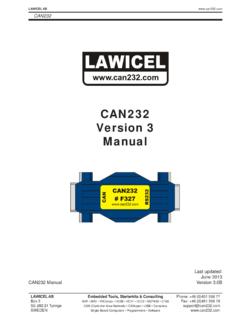
4 Connect a standard USB A-B Panel(1) CONTROL: RED color indicates when radio sends data to computer (2) CONTROL: GREEN color indicates when computer sends data to radio (3) PTT: RED color indicates when PTT is active (4) CW: RED color indicates when CW is active(5) SQL: GREEN color indicates when squelch is active(6) POWER: YELLOW color indicates when unit is powered4microHAM 2016 All rights reserved4 - INSTALLATIONI nstalling USB Interface II consists of several steps: 1) prepare USB Interface II to work with your radio2) install microHAM USB Device Router (the control and Interface software)3) configure Router Preparing USB Interface II for Use the top cover from the USB Interface II and set the CAT jumpers as shown in the following chart. The CAT Interface jumpers must be configured to select the proper level for each radio levels: All transceivers with RS-232 CAT inputs. IF-232 levels:Kenwood: TS-140, 440, 450, 680, 690, 711,790, 811, 850, 940, 950 FIF-232 levels: Yaesu: FT-100, 736, 747, 757 GXII, 767, 817,840, 857, 890, 897, 900, 980, 990, 1000,1000 DCI-V levels: Icom: all radios TenTec: all rigs with jackNOTE: the CAT Interface is not configured at the the DB15M on the radio cable set into the DB15 connector on the rear panel of the DIGI KEYER and plug ALL connectors from the cable set to the appropriate jacks at the rear panel of your transceiver.
5 Each connector on the radio Interface cable is marked same as the matching jack on your transceiver. the radio cable ends with leads for external power, connect these leads to a 12-16V DC power supply. Be sure to observe the proper but do not connect the USB cable from USB Interface II to your computer. you will be installing on a Windows computer, skip to Installing microHAM USB Router 5IF232CI-VFIF232RS232microHAM 2016 All rights reservedMac OS X the microHAM CD in yourCDROM/DVD drive and navigate toDrivers/OS-X or use your web browser to goto down load the latest driver image clicking on it. OS-X , or openFTDIUSBS erialDriver_10_4_10_5_10_6and follow the instructions to install. in the USB cable on the radio or external power supply. your software developer's instructions to configure their application to work with USB Interface III. MICROSOFT WINDOWS INSTALLATIONI nstalling microHAM USB Device Router install Router click on the Install USB Device Router link on the installation CD or download the most recent installation package from the web site: you download an updated package, right click on " " (xx_xx is version) and choose Run as administrator to start Windows setup utility will start and ask intowhich folder Router and its supporting files shouldbe installed.
6 Note: unless you have a very strongreason to install Router elsewhere, please acceptthe default location. the Router installation is completed, click"Finish" to launch Router for the first time. in the USB cable and proceed to configuring Router for your station and software. 6microHAM 2016 All rights reservedConfiguring microHAM USB Device Router The microHAM USB Device Router (Router) program provides a Windows compatible configuration tool for microHAM USB Devices (USB Interface II as well as microKEYER, CW Keyer and USB Interfaces) and software Interface to other Windows applications (loggers, digital mode software, etc.). The software Interface is provided as Virtual Serial configure and use USB Interface II with Windows compatible application programs it is necessary to have installed the USB driver, started the Router, and applied power to USB Interface II by turning on the attached radio or external power supply. Router is then configured to match the requirements of the application (logger or digital mode) software.
7 USB Interface II Status When the USB driver is installed correctly Router will show a device tab with a GREEN check beside the device name (USB Interface II). The yellow POWER LED must also be ON for USB IIto operate properly. DO NOT proceed with setup unless you have both a green check and the yellow POWER LED is ON. Creating and Using Virtual Serial Ports microHAM Router provides a set of virtual serial ports which allow Windows applications (loggers and digitalsoftware) to work with USB Interface II just as they would work with "real" (hardware) serial ports. In order to use these virtual Ports, you must first create the ports and then assign a function (radio control, PTT, CW, FSK, etc.) to each virtual port. DO NOT define a port that is already in use (for example, COM1 or COM2 which are hardware ports on many motherboards) or a virtual port used by another USB device. Router will not allow using a COM port number which is already present in the system but ports are sometimes hdden.
8 If a another device which also uses virtual serial ports (external USB devices, bluetooth devices, PDA etc ..) is not connected to the computer whencreating virtual ports in Router, the ports can overlap and will not workproperly when you connect such device. IMPORTANT WARNING: Before creating virtual COM ports, attach all external devices you will use with the computer. Restart Router and then create the virtual COM ports are created fromthe Virtual Port menu. Create - Creates virtual COMports. It is possible to selectmore than one port at a time by holding the Ctrl key andclicking several port numbers. Creating virtual ports may take a while, be 2016 All rights reservedDelete - Deletes any single virtual All - Deletes all previously created virtual not delete a virtual port until all applications using that port have been : It is possible to select multiple ports at one time by holding Ctrl key on keyboard and clicking onthe COM port numbers. TIP: If you have uninstalled another device which used virtual ports and Router does not offer the released COM port number you will need to reset the virtual port bus.
9 You can do this by deleting allvirtual ports in Router at once. Select "Virtual Port | Delete All" then create the ports again. Any missing COM port number should 2016 All rights reserved 5 - microHAM USB DEVICE ROUTERROUTER MENU Default Router Settings: used to completely reset Router to factory (default) settings. "Default" removes all device tabs and deletes all stored configuration data, including all user presets. from the Windows Registry. Restore Router Settings: used to restore settings from a urs file created by the backup command. A urs file can be used only with the device for which it was generated (the file contains the unit serial number) on a computer with same port assignments. WARNING: Restoring a backup replaces all current Router settings including presets, use it carefully! Backup Router Settings: used to create backup urs file. This file contains Router settings (including Presets) for all devices defined in | General - Load Router on Start-up: when checked, Router will start automatically each time the computer isstarted or rebooted.
10 - Start Router Minimized: when checked, Router will started minimized Options | Band Map: - Does not apply to USB Interface II - Customizable band edge boundaries used to drive the band data output. BCD codes can be customized for driving antenna switches or bandpass filter control. This setting is not used with USB Interface | Digital Band Map: - Does not apply to USB Interface II - Customizable band boundaries for the digital mode operation. These settings are used for the (optional)automatic selection of audio switching and PTT mode based on operating freuquency. Careful selectionof the "Digital band" is neccessary for transceivers which do not have a special mode for AFSK operation or do not report the mode in the computer command set. This primarily effects Kenwood and TenTec transceivers although it applies to some older Icom and Yaesu radios. Options | Audio Devices: - Don't use audio devices: when checked, Router does not use audio devices and the settings on the Audio Mixer and DVK tabs have no Manualy assign audio devices: when checked, Router will allow the user to select audio devices (sound card) in the appropriate fields at Audio Mixer tab and will actively control the audio devices- Automaticaly assign microHAM audio devices: when checked, Router will automatically assign proper audio device of the same name if multiple microHAM interfaces of the same kind are connected to the one computer.